The Electronics Pod Assembly (EPOD)
17-16 DSX™ System Service Manual
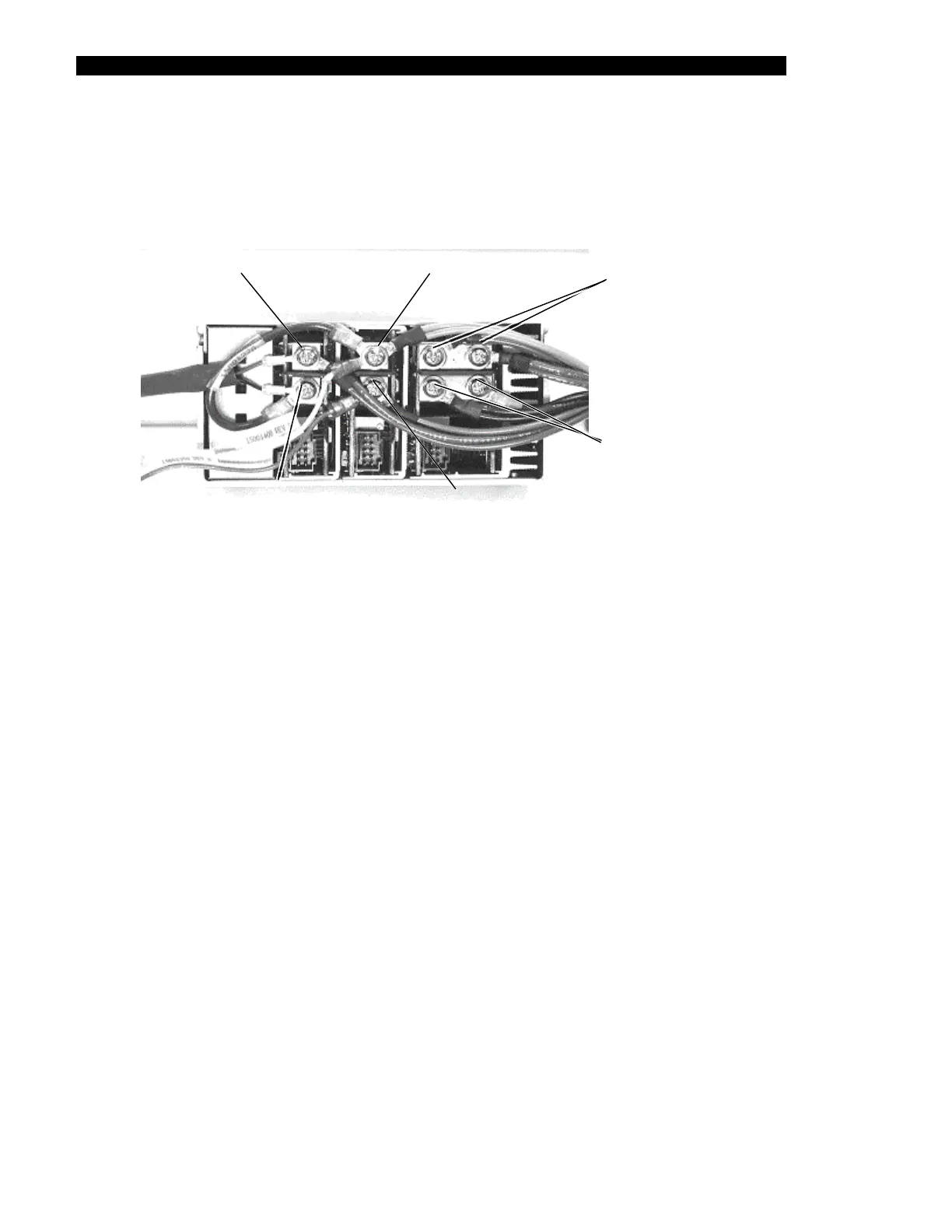
3 Remove the backplane harness (Part No. 15001250) and PSU harness
(Part No. 412001900) from the DC output terminals of the Power Supply Unit
(Figure 17-15).
harness & re
V3 Positive
rown wires of
d fan wire
V2 Positive
(Double orange wires, short blue
harness, &
ellow wire end
V1 Positive
(Double red wires of
harness)
V2 Negative
(Double grey wires of harness,
and small lug of blue wire)
V3 Negative
(End of short blue
ess & black fan wire)
V1 Negative
(Black wires of harness,
double wires on left,
single wire on right)
harn
(Double b
Figure 17-15 DC Output Terminals
To Reinstall the Power Supply Unit:
1 Connect the Back Plane harness, PSU harness and DC output terminals as
follows:
a) Attach two double red wires of harness to V1 POSITIVE (one ring terminal to
each screw).
b) Attach black wires of harness to V1 NEGATIVE (double wires on the left and
single wire on the right).
c) Attach double orange wires of harness with the short blue harness, and yellow
wire end of harness to V2 POSITIVE.
d) Attach double grey wires of harness and small lug end of blue wire to V2
NEGATIVE.
e) Attach double brown wires of harness (Part No. 15001250) and red wire from
fan to V3 POSITIVE.
f) Attach other end of the short blue harness (Part No. 15001270) and black wire
from fan to V3 NEGATIVE