Post-Service Checkout Protocol
3-14 DSX™ System Service Manual
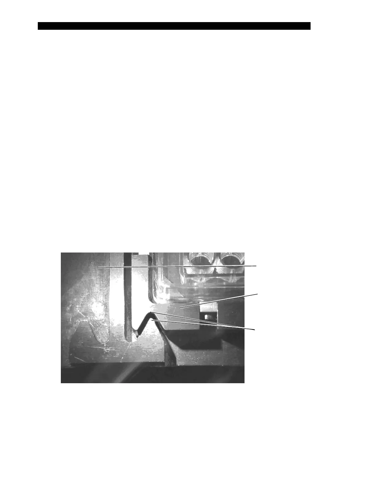
4 As clamping begins (i.e. the clamp body drives into the pick-up block), refer to
Figure 3-7 for correct positioning in the Y direction. Adjust the Y coordinate as
necessary. With the alignment Vees positioned as shown, the plate holder
assembly is approximately five to ten steps from the rear of the plate carrier.
This is the ideal positioning (i.e. with the plate holder closer to the rear of the
carrier than to the front).
5 Select Put Plate while observing the positioning of the plate carrier and the
plate holder assembly alignment Vees (Figure 3-7). They should align as
shown; if not, adjust the X or Y coordinates.
6 The optimal Z alignment is best observed as the plate is released during the
Put Plate operation. At the start of the command, the plate holder is held by the
pipette approximately 2.5 cm (1 inch) above the plate carrier. When the Put
Plate button is selected, the pipette moves down to place the plate holder into
the plate carrier after the drawer extends. At this point (i.e., before the plate is
unclamped), there should be approximately 0.5 mm (0.02 inch) between the
bottom of the holder and the top of the carrier. Adjust the Z coordinate to
achieve this gap.
7 Several attempts of putting and getting the plate may be required to obtain the
optimal results. When finished, click OK to save the values. If you make any
changes and exit without selecting OK, the values will not be saved.
Plate
Carrier
Plate
Holder
lignment
Vees
Figure 3-7 Plate Alignment Vees