Index6
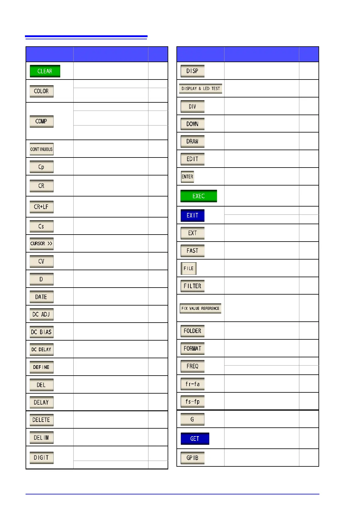
Clear all measurement values
saved to instrument memory
106,
219
Draw color setting 181
Saves screen copies as 256-
color BMP files.
341
Area judgment setting 197
Detail display of peak judg-
ment result
208
Configuring the equivalent cir-
cuit analysis comparator
260
Continuous measurement 265
Static capacitance in parallel
equivalent circuit mode (F)
25
Set terminator to CR
(Refer to the Communication
Instruction Manual (CD))
Set terminator to CR+LF
(Refer to the Communication
Instruction Manual (CD))
Static capacitance in series
equivalent circuit mode (F)
25
Cursor settings 188
Constant voltage sweep 135
Loss coefficient = tan
25
Save date and time setting 335
DC adjustment setting 75
DC bias setting 57
Delay time setting 82
Setting circuit element
constants
258
Delete segment 171
Trigger delay setting 64
Delete selected item
Delimiter type setting 334
Switch numerical input method
41,
158
Number of display digits setting 124
Key Description
Refer-
ence
LCD settings 127
Screen display test 310
Vertical axis width setting 185
Enable falling edge 117
Graph and list draw timing setting
139,
269
Change segment settings 169
Confirm entered numerical val-
ues
Start compensation
273,
280,
288
Check settings
Close setting screen
External trigger 56
High-speed measurement set-
ting
164
Save settings
315,
329
Filter setting
192,
211
Judgment area settings
(Reference value, upper limit
value, and lower limit value
settings)
202
Create folder 360
Format USB flash drive 357
Frequency setting 41
Frequency sweep 135
Resonant/anti-resonant fre-
quency setting
248
Series/parallel resonant fre-
quency setting
248
Conductance (S) 25
Set current compensation con-
ditions as load compensation
conditions
299
GP-IB setting 22
Key Description
Refer-
ence