3 - 15
Chapter 3 Removal and Replacement Procedures (RRPs)
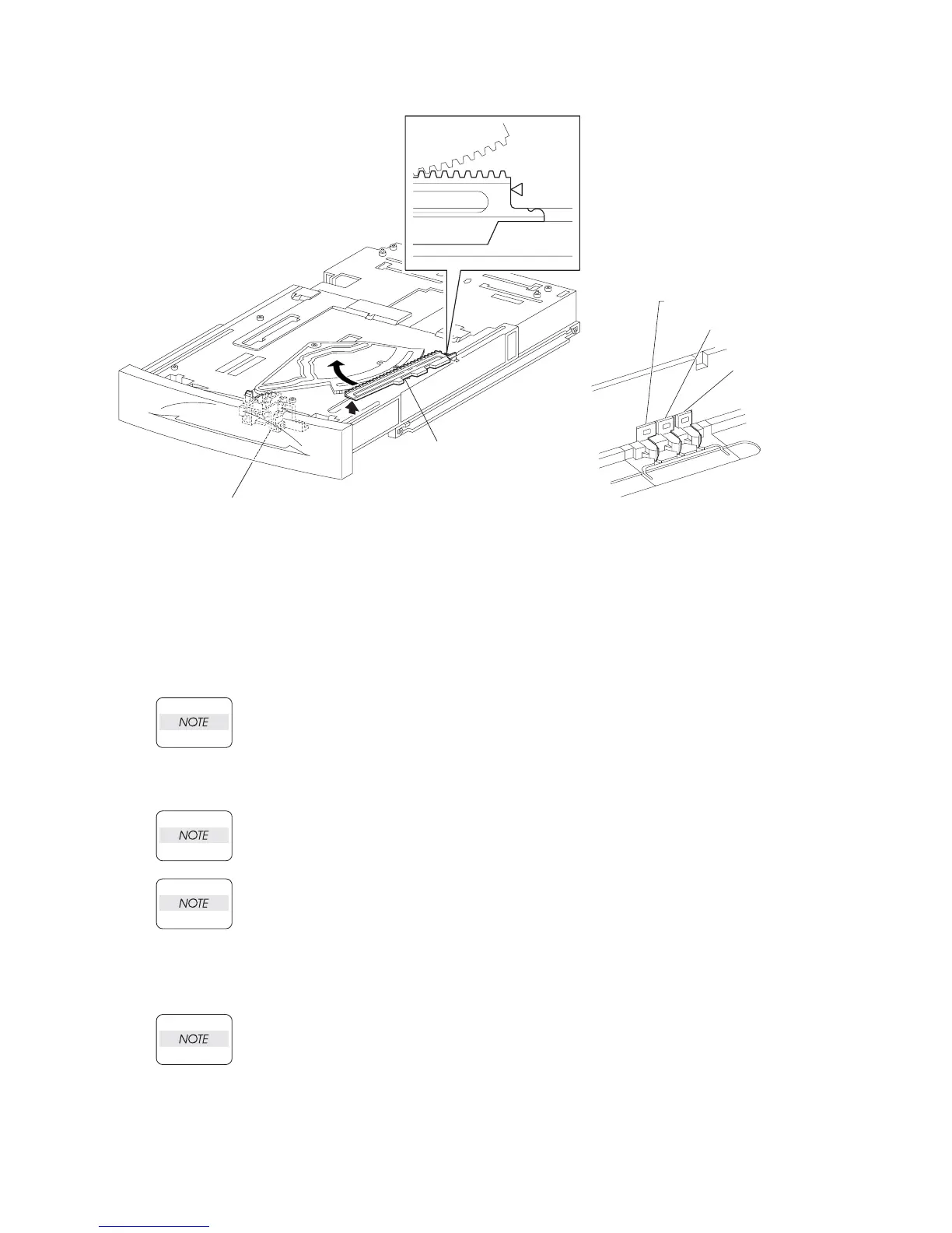
Figure 3. Size Rack
Replacement
1) Put the hook of the tip of the RACK SIZE (PL 2.1) into the groove of the HOUSING EXTENSION
150, and turn it in the opposite direction of the arrow.
2) Align the end of the RACK SIZE with the triangle mark printed on the HOUSING EXTENSION 150
as shown in the figure, and install the RACK SIZE to the HOUSING EXTENSION 150.
When installing the RACK SIZE, be sure to pull out the GUIDE ASSEMBLY END 150 (PL
2.1) as far as it will go. (NOTE 1) (Figure 3).
3) Install the COVER EXTENSION (PL 2.1) to the HOUSING EXTENSION 150 using the 4 screws
(gold tapping, 6mm).
When installing, make sure the COVER EXTENSION is inserted under 3 claws of the
HOUSING EXTENSION 150. (NOTE 2) (Figure 2).
Use 6mm size of fixed screw. If 8mm size of screw is used, HOUSING EXTENSION 150
doesn't operate smoothly and LOCK EXTENSION 150 doesn't operate correctly.
4) Install the HOUSING EXTENSION 150 and HOUSING TOP 150 (PL 2.1) to the HOUSING BASE
150 (PL 2.1) while pushing the LINK SW SIZE1-150 (PL 2.1), LINK SW SIZE2-150 (PL 2.1) and
LINK SW SIZE3-150 (PL) of the HOUSING BASE 150 outward as shown in the figure (Figure 3).
Be sure to put 2 claws on the top of the PLATE ASSEMBLY BTM under the hooks on the
HOUSING TOP 150. (NOTE 3) (Figure 1).
5) After assembling the HOUSING TOP 150 to 150 BASE HOUSING using the 4 hooks, secure them
using the 2 screws (gold tapping, 8mm) on both right and left sides, as well as the 6 screws (gold
tapping, 8mm) on the back.
RACK SIZE
(PL2.1.32)
GUIDE END 150
JG3009AA
JG3200AB
LINK SW SIZE 2 150
LINK SW SIZE 1 150
LINK SW SIZE 3 150