3 - 18
Chapter 3 Removal and Replacement Procedures (RRPs)
Replacement
1) Install the GEAR SECTOR to the HOUSING EXTENSION 150 (PL 2.1) (Figure 1).
2) Secure the GEAR SECTOR using the screw (black with flange, 8mm).
3) Install the RACK SIZE 150 (PL 2.1) (RRP2.2).
4) Install the COVER EXTENSION (PL 2.1) to the HOUSING EXTENSION 150 using the 4 screws
(gold tapping, 6mm).
When installing, make sure the COVER EXTENSION is inserted under 3 claws of the
HOUSING EXTENSION 150.
Use 6mm size of fixed screw. If 8mm size of screw is used, HOUSING EXTENSION
150 doesn't operate smoothly and LOCK EXTENSION 150 doesn't operate
correctly.
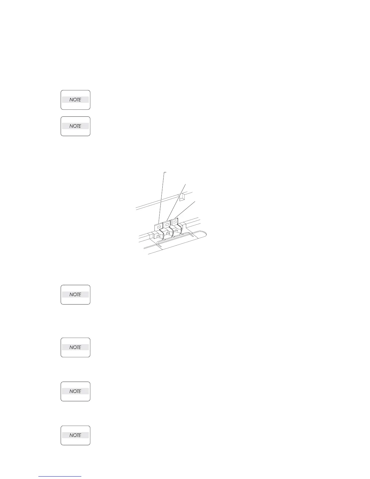
5) Install the HOUSING EXTENSION 150 and HOUSING TOP 150 (PL 2.1) to the HOUSING BASE
150 (PL 2.1) while pushing the LINK SW SIZE1-150 (PL 2.1), LINK SW SIZE2-150 (PL 2.1) and
LINK SW SIZE3-150 (PL 2.1) of the HOUSING BASE 150 outward as shown (Figure 2).
Figure 2. Link Size
Be sure to put 2 claws on the top of the PLATE ASSEMBLY BTM under the hooks on
the HOUSING TOP 150.
6) After assembling the HOUSING TOP 150 to HOUSING BASE 150 using the 4 hooks, secure them
using the 2 screws (gold tapping, 8mm) on both right and left sides, as well as the 6 screws (gold
tapping, 8mm) on the back.
After tightening the screws, move the GUIDE ASSEMBLY END 150 back and forth, and
make sure that the LINK SW SIZEs operate smoothly.
7) While pressing down the hook of the HOUSING TOP 150, install the GUIDE ASSEMBLY SD R150
(PL 2.1) to the HOUSING TOP 150.
After installing, make sure that the 3 claws of the GUIDE ASSEMBLY SD R150 sit
correctly in the grooves of the HOUSING TOP 150.
8) While pressing down the hook of the HOUSING TOP 150, install the GUIDE ASSEMBLY SD L150
(PL 2.1) to the HOUSING TOP 150.
After installing, make sure that the 3 claws of the GUIDE ASSEMBLY SD L150 sit
correctly in the grooves of the HOUSING TOP 150.
9) Push the PLATE ASSEMBLY BTM downward to lock.
JG3200AB
LINK SW SIZE 2 150
LINK SW SIZE 1 150
LINK SW SIZE 3 150