PRINTING SECTION
6-31
SM C231/C237/C238
Replacement
and
Adjustment
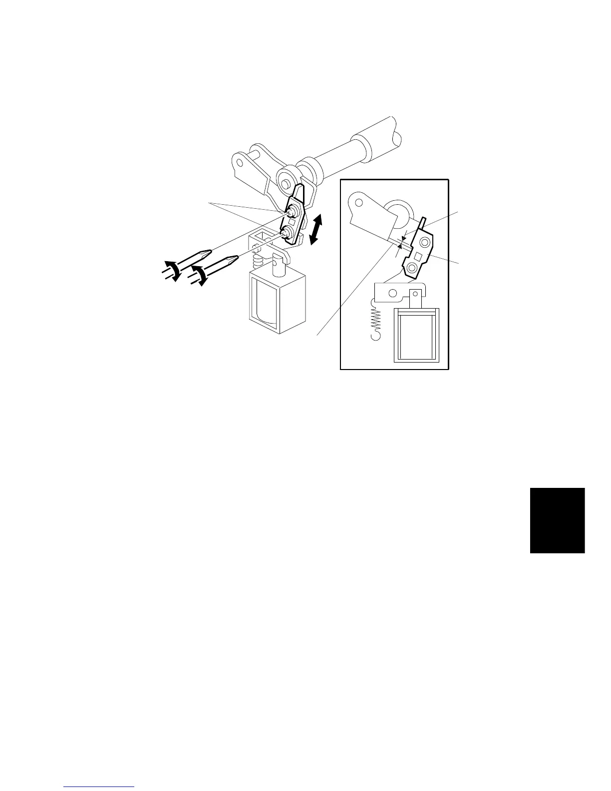
6. Using a thickness gauge, measure the clearance [A] between the press roller
arm [B] and press roller lock lever [C] (rear side). It should be between 0.7 and
1.2 mm.
7. If it is not correct, adjust the position of the press roller lock lever after
loosening the two screws [D].
8. Repeat steps 6 and 7 for the press roller lock lever located on the operation
side of the machine.
C231R525.WMF
[A]
[B]
[C]
[D]