Replacement
Adjustment
MASTER FEED SECTION
SM 6-1 C231/C237/C238
6. REPLACEMENT AND ADJUSTMENT
6.1 MASTER FEED SECTION
6.1.1 MASTER END SENSOR ADJUSTMENT
Purpose:
To ensure that the sensor detects the end mark (a solid black area) on the master
roll.
NOTE:
In the C237 model, the master end sensor input voltage, when detecting
the solid black area, was changed from 1.5
±
0.1 volts to 2.0
±
0.1 volts.
Adjustment standard:
Within 2.0
±
0.1 volts (when detecting the solid black area)
Within 3.7
±
0.1 volts (when detecting a new master roll)
1. Make a print that includes a solid-fill black area.
2. Open the scanner unit, and remove the master roll.
3. Position the print so that the solid black area faces the master end sensor.
4. Turn on the main switch and access the SP mode.
5. Select the master end sensor voltage mode (SP135), then press the Enter key.
6. The sensor input voltage is displayed on the operation panel. (If it is 2.0
±
0.1
volts, the following steps are not necessary.)
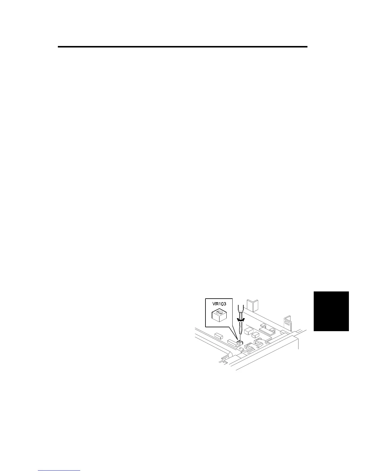
7. Open the scanner unit, and remove the MPU cover.
8. Adjust VR103 until the sensor input
voltage becomes 2.0
±
0.1 volts.
9. Remove the solid black pattern from
the master end sensor.
10. Install a new master roll.
11. The sensor input voltage is displayed
on the operation panel. Check that it is
3.7
±
0.1 volts.
C237R559.WMF


 To Next Page