SINUS PENTA
PROGRAMMING GUIDE
158/486
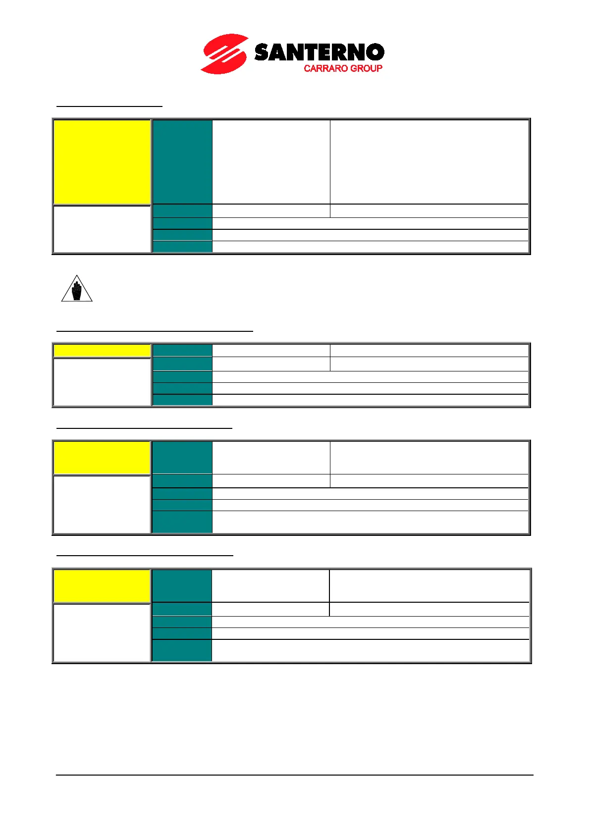
P184 AO2 Analog Output
P184 Range
0 ÷ 7
1: ± 10V,
2: 0 ÷ 10V,
3: 0 ÷ 20mA,
4: 4 ÷ 20mA,
5: ABS 0 ÷ 10V,
6: ABS 0 ÷ 20mA,
Selects the operating mode of AO2 analog output.
NOTE
Analog outputs are set as voltage outputs by default. To set them as current outputs, see
the DIP-switch configuration and follow the instructions displayed on the keypad, or refer to
the Sinus Penta’s Installation Guide.
P185 Selected Variable for AO2 Analog Output
Reference at constant speed
Selects the variable to be allocated to AO2 digital output.
P186 Min. Value of AO2 Selected Variable
P186 Range
–32000 ÷ +32000
Depends on the value
selected in P185
–320.00 % ÷ +320.00 % of the full-scale value
See Table 36
Function
Minimum value of the variable selected via P185, corresponding to the min.
output value of AO2 set in P190.
P187 Max. value of AO2 Selected Variable
P187 Range
–32000 ÷ +32000
Depends on the value
selected in P185
–320.00 % ÷ +320.00 % of the full-scale value
See Table 36
Function
Maximum value of the variable selected via P185, corresponding to the max.
output value of AO2 set in P191.