SINUS PENTA
PROGRAMMING GUIDE
160/486
NOTE
Analog outputs are set as voltage outputs by default. To set th
see the DIP-switch configuration and follow the instructions displayed on the keypad, or
refer to the Sinus Penta’s
Installation Guide.
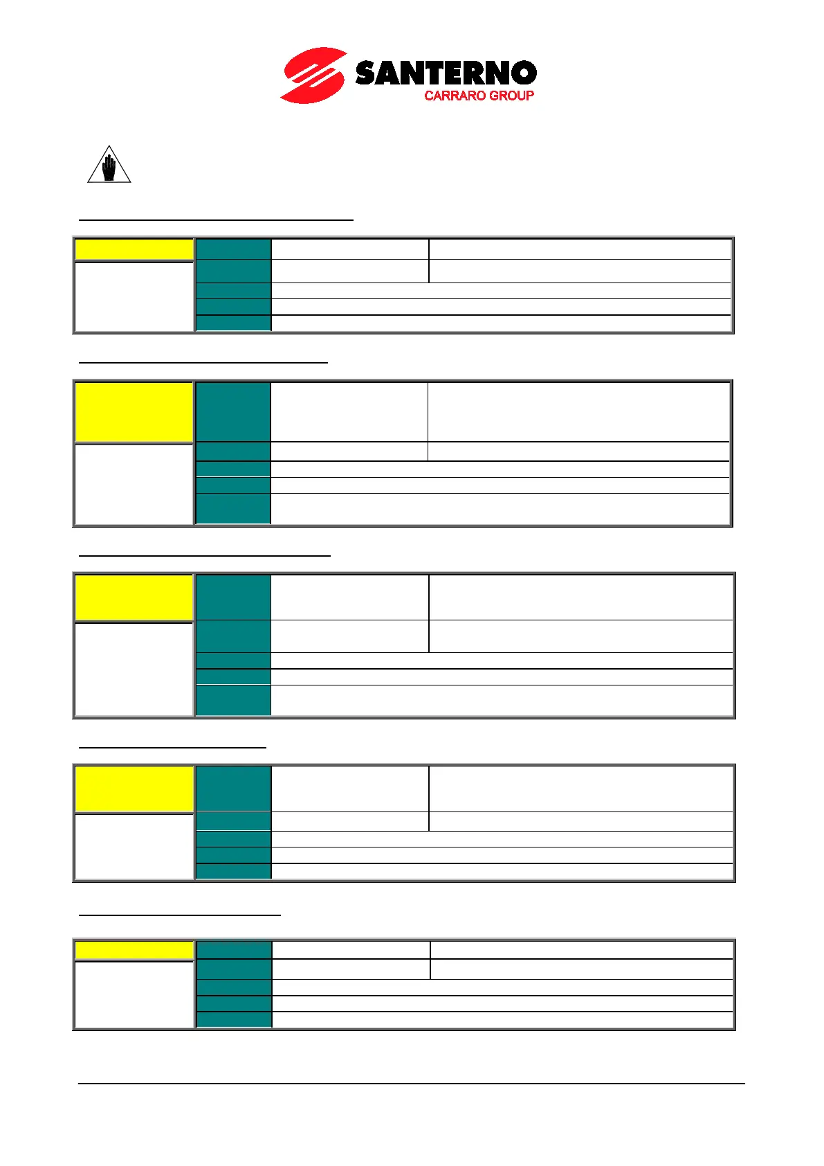
P193 Selected Variable for AO3 Analog Output
÷
5 5: Motor current
Selects the variable to be allocated to AO3 analog output.
P194 Min. Value of AO3 Selected Variable
P194 Range
of the full-scale value
Depends on the value
selected through P193
–320.00 % ÷ +320.00 % of the full-scale value
See Table 36
Function
Minimum value of the variable selected via P193, corresponding to the min.
output value of AO3 set in P198.
P195 Max. Value of AO3 Selected Variable
P195 Range
–320.00 % ÷ +320.00 %
Depends on the value
selected through P193
–320.00 % ÷ +320.00 % of the full-scale value
See Table 36
Default
Inverter Imax
Max. drive current depending on the drive size – see
Table 81 and Table 85
Function
Maximum value of the variable selected via P193, corresponding to the max.
output value of AO3 set in P199.
P196 AO3 Analog Output Offset
P196 Range
–9999 ÷ +9999
Depends on the value
selected through P192
–9.999 ÷ +9.999
Offset value applied to AO3 analog output.
P197 Filter for AO3 Analog Output
Value of the filter time constant applied to AO3 analog output.