Switch on SON
(Servo-on).
Refer to chapter 8 and remove cause.
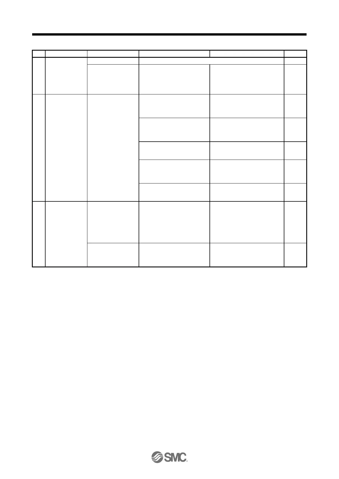
Servo motor shaft is
not servo-locked.
(Servo motor shaft is
free.)
1. Check the display to see if
the driver is ready to operate.
2. Check the external I/O signal
indication (section 4.5.7) to
see if SON (Servo-on) is on.
1. SON (Servo-on) is not input.
(wiring mistake)
2. 24 V DC power is not supplied
to DICOM.
Switch on ST1
(Forward rotation
start) or ST2
(Reverse rotation
start).
Servo motor does not
rotate.
Call the status display (section
4.5.3) and check the input
voltage of VC (Analog speed
command).
Analog speed command is 0 V.
Call the external I/O signal
display (section 4.5.7) and check
the on/off status of the input
signal.
LSP, LSN, ST1, and ST2 are off.
Check the internal speed
commands 1 to 7 ([Pr. PC05] to
[Pr. PC11]).
Check the forward rotation
torque limit ([Pr. PA11]) and the
reverse rotation torque limit ([Pr.
PA12]).
Torque limit level is too low as
compared to the load torque.
When TLA (Analog torque limit)
is usable, check the input
voltage on the status display.
Torque limit level is too low as
compared to the load torque.
Rotation ripples (speed
fluctuations) are large
at low speed.
Make gain adjustment in the
following procedure.
1. Increase the auto tuning
response level.
2. Repeat acceleration and
deceleration three times or
more to complete auto tuning.
Large load inertia
moment causes the
servo motor shaft to
oscillate side to side.
If the servo motor may be run
with safety, repeat acceleration
and deceleration three times or
more to complete auto tuning.

 Loading...