4. STARTUP
4 - 8
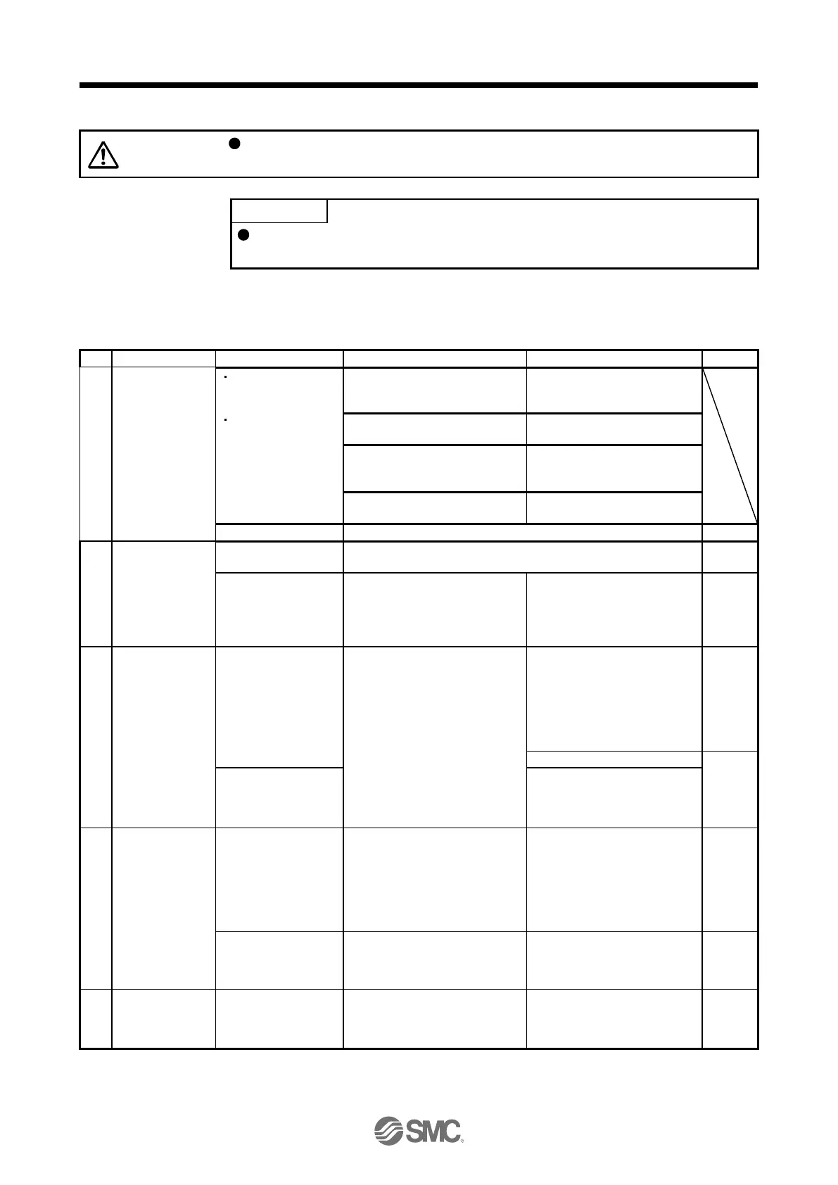
4.2.6 Trouble at start-up
Never adjust or change the parameter values extremely as it will make operation
unstable.
Using the optional Setup software (MR Configurator2
TM
), you can refer to reason
for rotation failure, etc.
The following faults may occur at start-up. If any of such faults occurs, take the corresponding action.
(1) Troubleshooting
The 5-digit,
7-segment LED is
not lit.
The 5-digit,
7-segment LED
blinks.
Not improved even if CN1, CN2
and CN3 connectors are
disconnected.
1. Power supply voltage fault
2. The driver is malfunctioning.
Improved when CN1 connector is
disconnected.
Power supply of CN1 cabling is
shorted.
Improved when CN2 connector is
disconnected.
1. Power supply of encoder
cabling is shorted.
2. Encoder is malfunctioning.
Improved when CN3 connector is
disconnected.
Power supply of CN3 cabling is
shorted.
Refer to chapter 8 and remove cause.
Switch on SON
(Servo-on).
Refer to chapter 8 and remove cause.
Servo motor shaft is
not servo-locked.
(Servo motor shaft is
free.)
1. Check the display to see if the
driver is ready to operate.
2. Check the external I/O signal
indication (section 4.5.7) to see
if SON (Servo-on) is on.
1. SON (Servo-on) is not input.
(wiring mistake)
2. 24 V DC power is not
supplied to DICOM.
Input command
pulse.
(Test operation)
Servo motor does not
rotate.
Check the cumulative command
pulse on the status display
(section 4.5.3).
1. Wiring mistake
(a) For open collector pulse
train input, 24 V DC power
is not supplied to OPC.
(b) LSP and LSN are not on.
2. Pulse is not input from the PC
or PLC...etc.
Mistake in setting of [Pr. PA13].
Servo motor run in
reverse direction.
1. Mistake in wiring to PC or
PLC...etc.
2. Mistake in setting of [Pr.
PA14].
Rotation ripples (speed
fluctuations) are large
at low speed.
Make gain adjustment in the
following procedure.
1. Increase the auto tuning
response level.
2. Repeat acceleration and
deceleration three times or
more to complete auto tuning.
Large load inertia
moment causes the
servo motor shaft to
oscillate side to side.
If the servo motor may be run with
safety, repeat acceleration and
deceleration three times or more
to complete auto tuning.
Confirm the cumulative command
pulses, cumulative feedback
pulses and actual servo motor
position.
Pulse counting error, etc. due to
noise.

 Loading...