16.23 HOW TO SET THE ELECTRONIC GEAR
16.23.1 Electronic gear settings in the point table method and program method
(1) Setting [mm], [inch], or [pulse] with "Position data unit" of [Pr. PT01].
Adjust [Pr. PA06] and [Pr. PA07] so that the driver setting matches with the travel distance of the
machine.
P
t
: Servo motor encoder resolution: 4194304 [pulse/rev]
ΔS: Travel distance per servo motor revolution [mm/rev]/[inch/rev]/[pulse/rev]
CMX/CDV = P
t
/ΔS
Set the electronic gear within the following range. Setting out of the range will trigger [AL. 37 Parameter
error].
Electronic gear setting range
1/13825 < CMX/CDV < 16967
The following setting example explains how to calculate the electronic gear.
To calculate the electronic gear, the following specification symbols are
required.
Pb: Ball screw lead [mm]
1/n: Reduction ratio
Pt: Servo motor encoder resolution [pulse/rev]
ΔS: Travel distance per servo motor revolution [mm/rev]
(a) Setting example of a ball screw
Machine specifications
Ball screw lead Pb = 10 [mm]
Reduction ratio: 1/n = Z
1
/Z
2
= 1/2
Z
1
: Number of gear teeth on servo motor side
Z
2
: Number of gear teeth on load gear
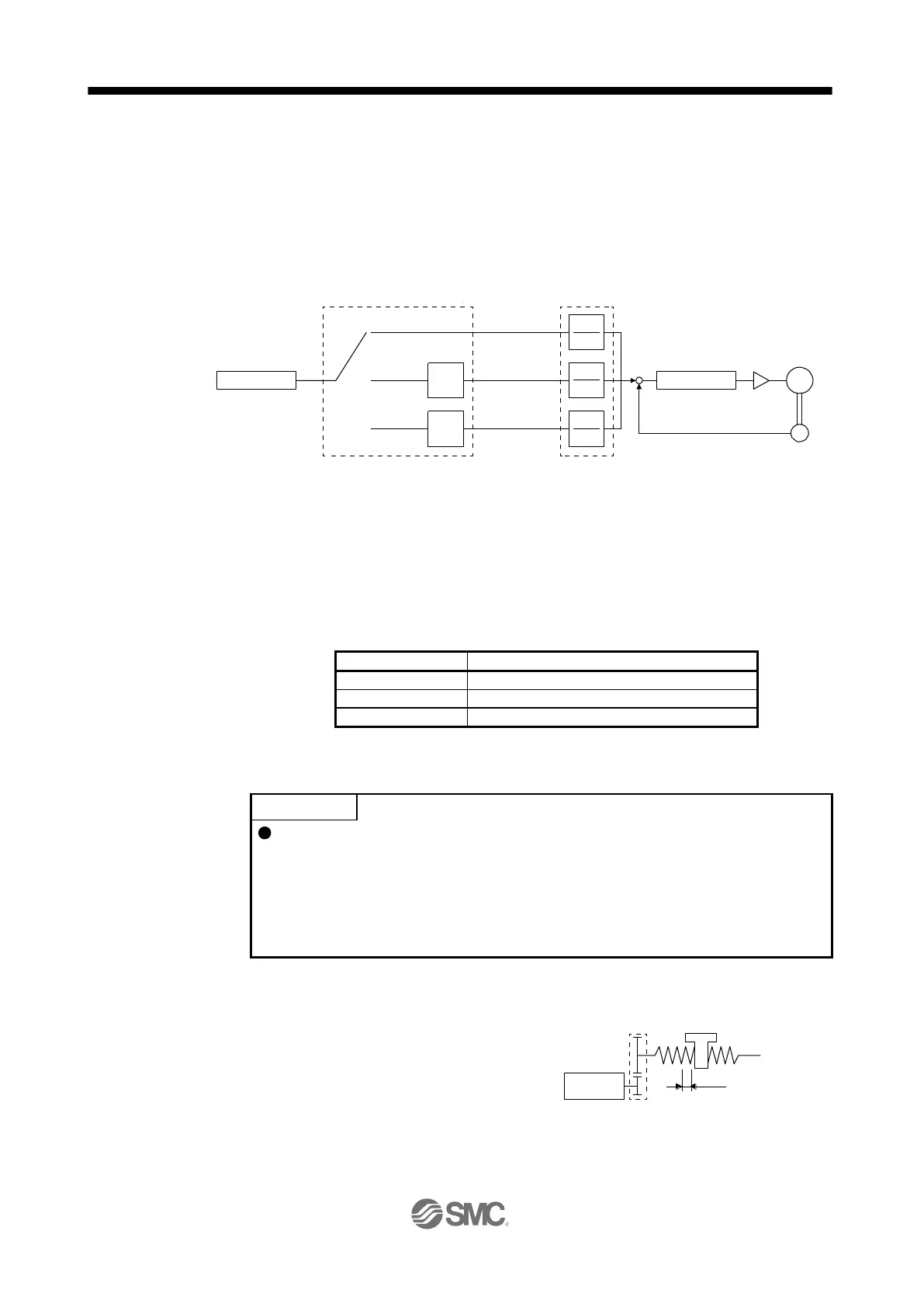
CDV
Travel distance
"0" (initial value)
CMX
CDV
CMX
Deviation counter
+
-
Electronic gear
([Pr. PA06]/[Pr. PA07])
Servo motor
Encoder
M
X32
X16
"2"
CDV
CMX
"3"
Electronic gear selection
(x _ _ _ ) ([Pr. PA21]) (Note)
Servo motor encoder resolution
4194304 [pulse/rev]
Pb = 10 [mm]
Z1
1/n = Z1/Z2 = 1/2
Z2
1/n

 Loading...