Home
SMC Networks
DC Drives
LECSB2-T Series
SMC Networks LECSB2-T Series User Manual
4
of 1
of 1 rating
945 pages
Give review
Manual
Specs
To Next Page
To Next Page
To Previous Page
To Previous Page
Loading...
14
.
COMMUN
ICATION FUNC
TION
14 -
32
14.
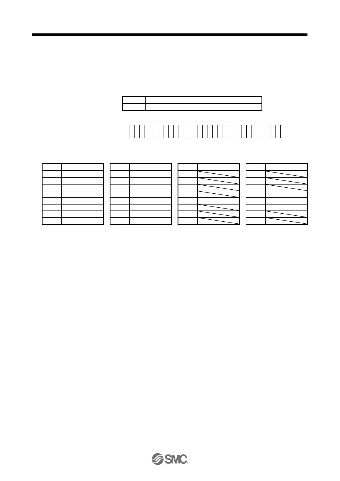
5.7 Input devices on/off
(test oper
ation)
Each input dev
ices can be turned on/off for test operation. However, w
hen the device to be switched off is in
the external input sign
al, also swi
tch off the input signal.
Transm
it com
mand [9] [2], data No. [0] [0], and da
ta.
Command
Data No.
Set data
[9] [2]
[0] [0]
See below.
b31
b1
b0
1
:
O
n
0
:
O
ff
Co
m
m
a
n
d
o
f
e
a
ch
b
i
t
is t
r
a
n
sm
itt
e
d
t
o
th
e
m
a
ste
r
sta
tio
n
a
s h
e
x
a
d
e
cim
a
l
d
a
ta
.
Bit
Symbol
Bit
Symbol
Bit
Symbol
Bit
Symbol
0
SON
8
SP1
16
24
1
LSP
9
SP2
17
25
2
LSN
10
SP3
18
26
3
TL
11
ST1
19
27
CDP
4
TL1
12
ST2
20
STAB2
28
CLD
5
PC
13
CM1
21
29
MECR
6
RES
14
CM2
22
30
7
CR
15
LOP
23
31
485
487
Table of Contents
1.Safety Instructions
2
CONTENTS
10
1.FUNCTIONS AND CONFIGURATION
22
1. FUNCTIONS AND CONFIGURATION
23
1.1 Summary
23
1.2 Function block diagram
24
1.3 Driver standard specifications
26
1.4 Combinations of driver and servo motors
28
1.5 Function list
29
1.6 Model designation
32
1.7 Structure
35
1.7.1 Parts identification
35
1.8 Configuration including peripheral equipment
36
2.INSTALLATION
38
2. INSTALLATION
39
2.1 Installation direction and clearances
40
2.2 Keep out foreign materials
41
2.3 Encoder cable stress
42
2.4 Inspection items
42
2.5 Parts having service lives
43
2.6 Restrictions when using this product at altitude exceeding 1000 m and up to 2000 m above sea level
43
3.SIGNALS AND WIRING
45
3. SIGNALS AND WIRING
46
3.1 Input power supply circuit
47
3.2 I/O signal connection example
50
3.2.1 Position control mode
50
3.3 Explanation of power supply system
59
3.3.1 Signal explanations
59
3.3.2 Power-on sequence
60
3.3.3 Wiring CNP1, CNP2, and CNP3
61
3.4 Connectors and pin assignment
63
3.5 Signal (device) explanations
66
3.6 Detailed explanation of signals
76
3.6.1 Position control mode
76
3.6.2 Speed control mode
81
3.6.3 Torque control mode
83
3.6.4 Position/speed control switching mode
86
3.6.5 Speed/torque control switching mode
88
3.6.6 Torque/position control switching mode
90
3.7 Forced stop deceleration function
91
3.7.1 Forced stop deceleration function
91
3.7.2 Base circuit shut-off delay time function
93
3.7.3 Vertical axis freefall prevention function
94
3.7.4 Residual risks of the forced stop function (EM2)
94
3.8 Alarm occurrence timing chart
95
3.8.1 When you use the forced stop deceleration function
95
3.8.2 When you do not use the forced stop deceleration function
96
3.9 Interfaces
97
3.9.1 Internal connection diagram
97
3.9.2 Detailed explanation of interfaces
99
3.9.3 Source I/O interfaces
103
3.10 Servo motor with a lock
105
3.10.1 Safety precautions
105
3.10.2 Timing chart
107
3.10.3 Wiring diagrams (LE-□-□ series servo motor)
112
3.11 Grounding
113
4.STARTUP
114
4. STARTUP
115
4.1 Switching power on for the first time
116
4.1.1 Startup procedure
116
4.1.2 Wiring check
117
4.1.3 Surrounding environment
118
4.2 Startup in position control mode
119
4.2.1 Power on and off procedures
119
4.2.2 Stop
119
4.2.3 Test operation
120
4.2.4 Parameter setting
120
4.2.5 Actual operation
120
4.2.6 Trouble at start-up
121
4.3 Startup in speed control mode
123
4.3.1 Power on and off procedures
123
4.3.2 Stop
124
4.3.3 Test operation
125
4.3.4 Parameter setting
126
4.3.5 Actual operation
126
4.3.6 Trouble at start-up
126
4.4 Startup in torque control mode
128
4.4.1 Power on and off procedures
128
4.4.2 Stop
128
4.4.3 Test operation
129
4.4.4 Parameter setting
129
4.4.5 Actual operation
129
4.4.6 Trouble at start-up
130
4.5 Display and operation sections
131
4.5.1 Summary
131
4.5.2 Display flowchart
132
4.5.3 Status display mode
133
4.5.4 Diagnostic mode
137
4.5.5 Alarm mode
139
4.5.6 Parameter mode
140
4.5.7 External I/O signal display
142
4.5.8 Output signal (DO) forced output
145
4.5.9 Test operation mode
146
5.PARAMETERS
151
5. PARAMETERS
152
5.1 Parameter list
152
5.1.1 Basic setting parameters ([Pr. PA_ _ ])
153
5.1.2 Gain/filter setting parameters ([Pr. PB_ _ ])
154
5.1.3 Extension setting parameters ([Pr. PC_ _ ])
156
5.1.4 I/O setting parameters ([Pr. PD_ _ ])
158
5.1.5 Extension setting 2 parameters ([Pr. PE_ _ ])
159
5.1.6 Extension setting 3 parameters ([Pr. PF_ _ ])
161
5.2 Detailed list of parameters
162
5.2.1 Basic setting parameters ([Pr. PA_ _ ])
162
5.2.2 Gain/filter setting parameters ([Pr. PB_ _ ])
174
5.2.3 Extension setting parameters ([Pr. PC_ _ ])
188
5.2.4 I/O setting parameters ([Pr. PD_ _ ])
202
5.2.5 Extension setting 2 parameters ([Pr. PE_ _ ])
210
5.2.6 Extension setting 3 parameters ([Pr. PF_ _ ])
213
6.NOMAL GAIN ADJUSTMENT
216
6. NORMAL GAIN ADJUSTMENT
217
6.1 Different adjustment methods
217
6.1.1 Adjustment on a single driver
217
6.1.2 Adjustment using setup software (MR Configurator2TM)
218
6.2 One-touch tuning
219
6.2.1 One-touch tuning flowchart
221
6.2.2 Display transition and operation procedure of one-touch tuning
224
6.2.3 Caution for one-touch tuning
238
6.3 Auto tuning
239
6.3.1 Auto tuning mode
239
6.3.2 Auto tuning mode basis
240
6.3.3 Adjustment procedure by auto tuning
241
6.3.4 Response level setting in auto tuning mode
242
6.4 Manual mode
243
6.5 2gain adjustment mode
246
7.SPECIAL ADJUSTMENT FUNCTIONS
249
7. SPECIAL ADJUSTMENT FUNCTIONS
250
7.1 Filter setting
250
7.1.1 Machine resonance suppression filter
251
7.1.2 Adaptive filter II
254
7.1.3 Shaft resonance suppression filter
257
7.1.4 Low-pass filter
258
7.1.5 Advanced vibration suppression control II
258
7.1.6 Command notch filter
263
7.2 Gain switching function
265
7.2.1 Applications
265
7.2.2 Function block diagram
266
7.2.3 Parameter
267
7.2.4 Gain switching procedure
270
7.3 Tough drive function
274
7.3.1 Vibration tough drive function
274
7.3.2 Instantaneous power failure tough drive function
276
7.4 Compliance with SEMI-F47 standard
280
7.5 Model adaptive control disabled
282
7.6 Lost motion compensation function
283
7.7 Super trace control
286
8.TROUBLESHOOTING
288
8. TROUBLESHOOTING
289
8.1 Explanation for the lists
289
8.2 Alarm list
290
8.3 Warning list
299
8.4 Remedies for alarms
302
8.5 Remedies for warnings
343
8.6 Trouble which does not trigger alarm/warning
359
9.OUTLINE DRAWINGS
368
9. OUTLINE DRAWINGS
369
9.1 Driver
369
9.2 Connector
372
10.CHARACTERISTICS
373
10. CHARACTERISTICS
374
10.1 Overload protection characteristics
374
10.2 Power supply capacity and generated loss
375
10.3 Dynamic lock characteristics
377
10.3.1 Dynamic lock operation
377
10.3.2 Permissible load to motor inertia when the dynamic lock is used
378
10.4 Cable bending life
379
10.5 Inrush currents at power-on of main circuit and control circuit
379
11.OPTIONS AND PERIPHERAL EQUIPMENT
380
11. OPTIONS AND PERIPHERAL EQUIPMENT
381
11.1 Cable/connector sets
381
11.1.1 Combinations of cable/connector sets
382
11.1.2 STO cable
385
11.1.3 Encoder cable/connector sets
386
11.1.4 Motor cables
388
11.1.5 Lock cables
389
11.2 Regenerative options
390
11.2.1 Combination and regenerative power
390
11.2.2 Parameter setting
390
11.2.3 Selection of regenerative option
391
11.2.4 Dimensions
392
11.3 Setup software (MR Configurator2TM)
393
11.3.1 Specifications
393
11.3.2 System configuration
394
11.3.3 Precautions for using USB communication function
395
11.4 Battery (LEC-MR-BAT6V1SET)
396
11.5 Selection example of wires
397
11.6 Molded-case circuit breakers, fuses, magnetic contactors (recommended)
399
11.7 Relay (recommended)
399
11.8 Noise reduction techniques
400
11.9 Earth-leakage current breaker
407
11.10 EMC filter (recommended)
409
12.ABSOLUTE POSITION DETECTION SYSTEM
413
12. ABSOLUTE POSITION DETECTION SYSTEM
414
12.1 Summary
414
12.1.1 Features
414
12.1.2 Restrictions
414
12.1.3 Structure
415
12.1.4 Parameter setting
415
12.1.5 Confirmation of absolute position detection data
416
12.2 Battery
417
12.3 Standard connection example
418
12.4 Signal explanation
419
12.5 Startup procedure
420
12.6 Absolute position data transfer protocol
421
12.6.1 Data transfer procedure
421
12.6.2 Transfer method
422
12.6.3 Home position setting
431
12.6.4 Use of servo motor with an electromagnetic lock
433
12.6.5 How to process the absolute position data at detection of stroke end
434
12.7 Absolute position data transfer errors
434
12.8 Communication-based absolute position transfer system
436
12.8.1 Serial communication command
436
12.8.2 Absolute position data transfer protocol
436
12.9 Battery replacement procedure
440
13.USING STO FUNCTION
442
13. USING STO FUNCTION
443
13.1 Introduction
443
13.1.1 Summary
443
13.1.2 Terms related to safety
443
13.1.3 Cautions
443
13.1.4 Residual risks of the STO function
444
13.1.5 Specifications
445
13.1.6 Maintenance
446
13.2 STO I/O signal connector (CN8) and signal layouts
446
13.2.1 Signal layouts
446
13.2.2 Signal (device) explanations
447
13.2.3 How to pull out the STO cable
447
13.3 Connection example
448
13.3.1 Connection example for CN8 connector
448
13.3.2 External I/O signal connection example using an MR-J3-D05 safety logic unit of Mitsubishi Electric Corporation
449
13.3.3 External I/O signal connection example using an external safety relay unit
451
13.4 Detailed description of interfaces
452
13.4.1 Sink I/O interface
452
13.4.2 Source I/O interface
454
14.COMMUNICATION FUNCTION
455
14. COMMUNICATION FUNCTION
456
14.1 Structure
457
14.1.1 Configuration diagram
457
14.1.2 Precautions for using RS-422/RS-232C/USB communication function
459
14.2 Communication specifications
460
14.2.1 Outline of communication
460
14.2.2 Parameter setting
460
14.3 Protocol
461
14.3.1 Transmission data configuration
461
14.3.2 Character codes
462
14.3.3 Error codes
463
14.3.4 Checksum
463
14.3.5 Time-out processing
463
14.3.6 Retry processing
464
14.3.7 Initialization
464
14.3.8 Communication procedure example
465
14.4 Command and data No. list
466
14.4.1 Reading command
466
14.4.2 Writing commands
472
14.5 Detailed explanations of commands
474
14.5.1 Data processing
474
14.5.2 Status display mode
475
14.5.3 Parameter
476
14.5.4 External I/O signal status (DIO diagnosis)
481
14.5.5 Input device on/off
484
14.5.6 Disabling/enabling I/O devices (DIO)
485
14.5.7 Input devices on/off (test operation)
486
14.5.8 Test operation mode
487
14.5.9 Output signal pin on/off (output signal (DO) forced output)
491
14.5.10 Alarm history
492
14.5.11 Current alarm
493
14.5.12 Other commands
494
15.SERVO MOTOR
495
15. SERVO MOTOR
496
15.1 Servo motor with a lock
496
15.1.1 Features
496
15.1.2 Characteristics of servo motor with a lock
498
15.2 Protection from oil and water
499
15.3 Cable
499
15.4 Rated speed of servo motor
499
15.5 Mounting connectors
500
16.POSITIONING MODE
501
16. POSITIONING MODE
504
16.1 FUNCTIONS AND CONFIGURATION
504
16.1.1To use positioning mode
504
16.1.2 Positioning mode specification list
505
16.1.3 Function list
508
16.2 SIGNALS AND WIRING
512
16.2.1 I/O signal connection example
512
16.2.2 Connector and signal arrangement
518
16.2.3 Signal (device) explanations
521
16.2.4 Analog override
541
16.2.5 Internal connection diagram
543
16.2.6 Power-on sequence
546
16.3 DISPLAY AND OPERATION SECTIONS
547
16.3.1 Display sequence
547
16.3.2 Status display
549
16.3.3 Diagnostic mode
556
16.3.4 Alarm mode
559
16.3.5 Point table setting
561
16.3.6 Parameter mode
565
16.3.7 External I/O signal display
567
16.3.8 Output signal (DO) forced output
568
16.3.9 Single-Step feed
569
16.3.10 Teaching function
571
16.4 HOW TO USE THE POINT TABLE
572
16.4.1 Power on and off procedures
573
16.4.2 Stop
573
16.4.3 Test operation
574
16.4.4 Parameter setting
575
16.4.5 Point table setting
576
16.4.6 Actual operation
576
16.4.7 Troubleshooting at start-up
576
16.5 AUTOMATIC OPERATION MODE
578
16.5.1 Automatic operation mode
578
16.5.2 Automatic operation using point table
583
16.6 MANUAL OPERATION MODE
613
16.6.1 JOG operation
613
16.7 HOME POSITION RETURN MODE
615
16.7.1 Outline of home position return
615
16.7.2 Dog type home position return
618
16.7.3 Count type home position return
620
16.7.4 Data set type home position return
622
16.7.5 Stopper type home position return
623
16.7.6 Home position ignorance (servo-on position as home position)
625
16.7.7 Dog type rear end reference home position return
626
16.7.8 Count type front end reference home position return
628
16.7.9 Dog cradle type home position return
630
16.7.10 Dog type last Z-phase reference home position return
631
16.7.11 Dog type front end reference home position return type
632
16.7.12 Dogless Z-phase reference home position return type
634
16.7.13 Automatic retract function used for the home position return
635
16.7.14 Automatic positioning to home position function
636
16.8 ROLL FEED MODE USING THE ROLL FEED DISPLAY FUNCTION
637
16.9 POINT TABLE SETTING METHOD
639
16.9.1 Setting procedure
639
16.9.2 Detailed setting window
641
16.10 HOW TO USE THE PROGRAM
642
16.10.1 Power on and off procedures
642
16.10.2 Stop
643
16.10.3 Test operation
644
16.10.4 Parameter setting
645
16.10.5 Actual operation
646
16.10.6 Troubleshooting at start-up
646
16.11 PROGRAM OPERATION METHOD
647
16.11.1 Program operation method
647
16.11.2 Program language
648
16.11.3 Basic settings of signals and parameters
671
16.11.4 Timing chart of the program operation
673
16.12 MANUAL OPERATION MODE
675
16.12.1 JOG operation
675
16.12.2 Summary of home position return
677
16.12.3 Dog type home position return
680
16.12.4 Count type home position return
682
16.12.5 Data set type home position return
684
16.12.6 Stopper type home position return
685
16.12.7 Home position ignorance (servo-on position as home position)
686
16.12.8 Dog type rear end reference home position return
687
16.12.9 Count type front end reference home position return
689
16.12.10 Dog cradle type home position return
691
16.12.11 Dog type last Z-phase reference home position return
693
16.12.12 Dog type front end reference home position return type
695
16.12.13 Dogless Z-phase reference home position return type
697
16.12.14 Automatic retract function used for the home position return
698
16.13 SERIAL COMMUNICATION OPERATION
699
16.13.1 Positioning operation using the program
699
16.13.2 Multi-drop method (RS-422 communication)
700
16.13.3 Group specification
701
16.14 INCREMENTAL VALUE COMMAND METHOD
703
16.15 ROLL FEED MODE USING THE ROLL FEED DISPLAY FUNCTION
704
16.16 PROGRAM SETTING METHOD
705
16.16.1 Setting procedure
705
16.16.2 Window for program edit
706
16.16.3 Indirect addressing window
707
16.17 HOW TO USE INDEXER
708
16.17.1 Power on and off procedures
709
16.17.2 Stop
709
16.17.3 Test operation
710
16.17.4 Parameter setting
711
16.17.5 Actual operation
712
16.17.6 Troubleshooting at start-up
712
16.18 AUTOMATIC OPERATION MODE
714
16.18.1 Automatic operation mode
714
16.18.2 Automatic operation mode 1 (rotation direction specifying indexer)
715
16.18.3 Automatic operation mode 2 (shortest rotating indexer)
719
16.19 MANUAL OPERATION MODE
722
16.19.1 Station JOG operation
722
16.19.2 JOG operation
725
16.20 HOME POSITION RETURN MODE
727
16.20.1 Outline of home position return
727
16.20.2 Torque limit changing dog type home position return
729
16.20.3 Torque limit changing data set type
731
16.20.4 Backlash compensation and digital override
733
16.20.5 Safety precautions
736
16.21 PARAMETERS
737
16.21.1 Basic setting parameters ([Pr. PA_ _ ])
738
16.21.2 Gain/filter setting parameters ([Pr. PB_ _ ])
739
16.21.3 Extension setting parameters ([Pr. PC_ _ ])
741
16.21.4 I/O setting parameters ([Pr. PD_ _ ])
743
16.21.5 Extension setting 2 parameters ([Pr. PE_ _ ])
745
16.21.6 Extension setting 3 parameters ([Pr. PF_ _ ])
747
16.21.7 Positioning control parameters ([Pr. PT_ _ ])
748
16.22 DETAILED LIST OF PARAMETERS
749
16.22.1 Basic setting parameters ([Pr. PA_ _ ])
749
16.22.2 Gain/filter setting parameters ([Pr. PB_ _ ])
759
16.22.3 Extension setting parameters ([Pr. PC_ _ ])
771
16.22.4 I/O setting parameters ([Pr. PD_ _ ])
782
16.22.5 Extension setting 2 parameters ([Pr. PE_ _ ])
793
16.22.6 Extension setting 3 parameters ([Pr. PF_ _ ])
795
16.22.7 Positioning control parameters ([Pr. PT_ _ ])
797
16.23 HOW TO SET THE ELECTRONIC GEAR
807
16.23.1 Electronic gear settings in the point table method and program method
807
16.23.2 Electronic gear setting in the indexer method
810
16.24 SOFTWARE LIMIT
811
16.25 STOP METHOD FOR LSP (FORWARD ROTATION STROKE END) OFF OR LSN (REVERSE ROTATION STROKE END) OFF
812
16.26 STOP METHOD AT SOFTWARE LIMIT DETECTION
813
16.27 COMMUNICATION FUNCTION (MITSUBISHI GENERAL-PURPOSE AC SERVO PROTOCOL)
814
16.27.1 Reading command
814
16.27.2 Writing commands
825
16.28 DETAILED EXPLANATIONS OF COMMANDS
829
16.28.1 External I/O signal status (DIO diagnosis)
829
16.28.2 Input device on/off
834
16.28.3 Input device on/off (for test operation)
835
16.28.4 Test operation mode
836
16.28.5 Output signal pin on/off (output signal (DO) forced output)
838
16.28.6 Point table
839
16.29 APPLICATION OF FUNCTIONS
847
16.29.1 Current position latch function
847
16.29.2 Interrupt positioning function
853
17.Positioning mode (pushing operation)
857
17 Positioning mode (pushing operation)
858
17.1 Setup software (MR Configurator2TM)
858
17.1.1 Model information addition procedure
858
17.2 I/O signal connection example
861
17.3 Connector and signal arrangement
863
17.4 Signal (device) explanations
865
17.5 Explanation of forced stop deceleration function
870
17.5.1 Forced stop deceleration function
870
17.6 Explanation of torque limiting function
872
17.6.1 Torque limit and torque
872
17.6.2 Selection of torque limit value
872
17.6.3 TLC (Torque limited)
873
17.7 Point table type pushing operation
874
17.7.1 About Point table type pushing operation
874
17.7.2 Parameter setting
875
17.7.3 Point table
876
17.7.4 Point table data list
877
17.7.5 About pushing operation in the position address increasing direction
878
17.7.6 About pushing operation in the direction of decreasing position address
880
17.8 Pushing error detection
882
17.8.1 Missed swing motion detection
883
17.8.2 Push-back operation detection
885
17.8.3 Pushing direction error
889
17.8.4 When the positioning start position including the pushing operation is incorrect
889
17.8.5 When the point table setting value is incorrect
890
17.8.6 Pushing start error
892
17.8.7 When pushing operation is started independently
892
17.8.8 When the dwell is set immediately before the pushing operation
892
17.9 PARAMETERS
894
17.9.1 Positioning control parameters ([Pr. PT_ _ ])
894
17.9.2 Special setting parameter ([Pr.PS_ _])
896
17.10 Detailed list of parameters
897
17.10.1 Basic setting parameters ([Pr. PA_ _ ])
897
17.10.2 I/O setting parameters ([Pr. PD_ _ ])
898
17.10.3 Positioning control parameters ([Pr.PT_ _])
900
17.10.4 Special setting parameter ([Pr.PS_ _])
900
17.10.5 How to set the electronic gear
901
17.10.6 Software limit
901
17.10.7 Stop method for LSP(Forward rotation stroke end)off or LSN(Reverse rotation stroke end)Off
901
17.10.8 Stop method at software limit detection
901
17.11 Troubleshooting
902
17.11.1 Alarm list
902
17.11.2 Remedies for alarms
902
17.12 DISPLAY AND OPERATION SECTIONS
904
17.12.1 Point table setting
904
17.13 1 Single-Step feed
906
17.14 COMMUNICATION FUNCTION(Mitsubishi general-purpose AC servo protocol)
908
17.14.1 Reading command
908
17.14.2 Writing commands
909
17.14.3 Detailed explanations of commands
910
17.14.4 External I/O signal status (DIO diagnosis)
910
17.14.5 Input device on/off
911
17.14.6 Input device on/off (For test operation)
911
17.14.7 Test operation mode
911
17.14.8 Output signal pin on/off (output signal (DO) forced output)
911
17.14.9 Point table
911
APPENDIX
913
App. 1 Peripheral equipment manufacturer (for reference)
914
App. 2 Handling of AC driver batteries for the United Nations Recommendations on the Transport of Dangerous Goods
914
App. 3 Symbol for the new EU Battery Directive
916
App. 4 Compliance with global standards
917
App. 4.1 Terms related to safety (IEC 61800-5-2 Stop function)
917
App. 4.2 About safety
917
App. 4.2.1 Professional engineer
917
App. 4.2.2 Applications of the devices
917
App. 4.2.3 Correct use
917
App. 4.2.4 General cautions for safety protection and protective measures
920
App. 4.2.5 Residual risk
920
App. 4.2.6 Disposal
920
App. 4.2.7 Lithium battery transportation
921
App. 4.3 Mounting/dismounting
921
App. 4.4 Electrical Installation and configuration diagram
922
App. 4.5 Signal
923
App. 4.5.1 Signal
923
App. 4.5.2 I/O device
923
App. 4.6 Maintenance and service
924
App. 4.6.1 Inspection items
924
App. 4.6.2 Parts having service lives
925
App. 4.7 Transportation and storage
926
App. 4.8 Technical data
927
App. 4.8.1 LECSB2-T□ driver
927
App. 4.8.2 Driver dimensions
927
App. 4.8.3 Mounting hole
927
App. 4.9 Check list for user documentation
928
App. 5 MR-J3-D05 Safety logic unit of Mitsubishi Electric Corporation
928
App. 5.1 Terms related to safety
928
App. 5.1.1 Stop function for IEC/EN 61800-5-2
928
App. 5.1.2 Emergency operation for IEC/EN 60204-1
928
App. 5.2 Cautions
929
App. 5.3 Residual risk
929
App. 7 Analog monitor
930
App. 8 STO function with SIL 3 certification
934
App. 9 Status of compliance with the China RoHS directive
935
App. 10 Encoder output pulse setting method
936
App .11 Recommended parameter values for each actuator
937
4
Based on 1 rating
Ask a question
Give review
Questions and Answers:
Need help?
Do you have a question about the SMC Networks LECSB2-T Series and is the answer not in the manual?
Ask a question
SMC Networks LECSB2-T Series Specifications
General
Brand
SMC Networks
Model
LECSB2-T Series
Category
DC Drives
Language
English