EasyManuals Logo

SMC Networks LECSB2-T Series User Manual

SMC Networks LECSB2-T Series
945 pages
To Next Page IconTo Next Page
To Previous Page IconTo Previous Page
Page #541 background imageLoading...
Page #541 background image
16 - 41
16. POSITIONING MODE
16.2.4 Analog override
POINT
The override function has two types. One is analog override by using analog
voltage input and another is digital override by using parameter settings.
Target method of analog override: Point table method/Program method
Target method of digital override: Indexer method
OVR (Analog override selection) is for the analog override. The digital override
does not depend on OVR (Analog override selection).
Refer to [Pr. PT38], [Pr. PT42], and [Pr. PT43] for the digital override.
When using the analog override in the point table method or program method,
enable OVR (Analog override selection).
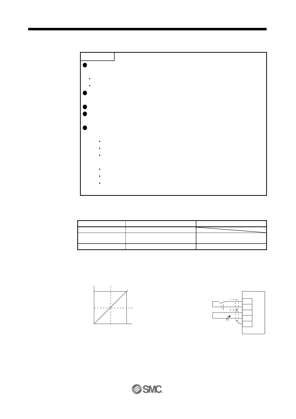
The following shows functions whether usable or not with the analog override.
(1) Analog override usable
Automatic operation mode (point table method/program method)
JOG operation in the manual operation mode
Automatic positioning to home position function in the point table method
(2) Analog override unusable
Manual pulse generator operation in the manual operation mode
Home position return mode
Test operation mode using setup software (MR Configurator2
TM
)
(positioning operation/JOG operation)
You can change the servo motor speed by using VC (Analog override). The following table shows signals
and parameters related to the analog override.
Item
Name
Remark
Analog input signal
VC (Analog override)
Contact input signal
OVR (Analog override selection)
Turning on OVR will enable VC
(Analog override) setting value.
Parameter
[Pr. PC37 Analog override offset]
-9999 to 9999 [mV]
(1) VC (Analog override)
You can continuously set changed values from outside by applying voltage (-10 V to +10 V) to VC
(Analog override). The following shows percentage of the actual speed to input voltage and set speed.
Note.
This diagram shows sink input interface.
-10 0 10 [V]
0
100
200
[%]
VC (Analog override voltage) applied voltage
OVR
DICOM
VC
LG
SD
Servo amplifier
OVR (Analog override selection)
VC (Analog override)
-10 V to +10 V
(Note)
24 V DC
Percentage of the actual
speed to set speed.
driver

Table of Contents

Questions and Answers:

Question and Answer IconNeed help?

Do you have a question about the SMC Networks LECSB2-T Series and is the answer not in the manual?

SMC Networks LECSB2-T Series Specifications

General IconGeneral
BrandSMC Networks
ModelLECSB2-T Series
CategoryDC Drives
LanguageEnglish