16.17.5 Actual operation
Start actual operation after confirmation of normal operation by test operation and completion of the
corresponding parameter settings.
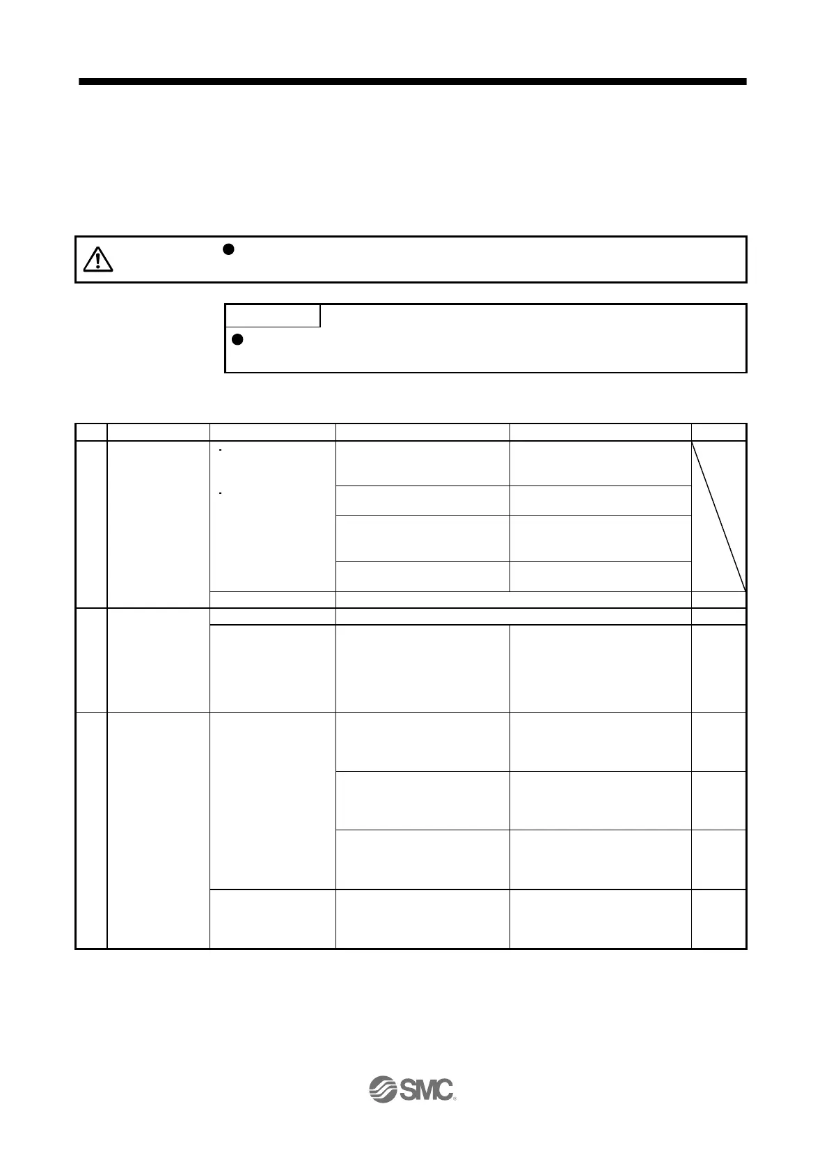
16.17.6 Troubleshooting at start-up
Never make a drastic adjustment or change to the parameter values as doing so
will make the operation unstable.
Using Setup software (MR Configurator2
TM
), you can refer to reason for rotation
failure, etc.
The following faults may occur at start-up.
The 7-segment LED
display does not turn
on.
The 7-segment LED
display flickers.
Not improved even if CN1, CN2,
and CN3 connectors are
disconnected.
1. Power supply voltage fault
2. The driver is malfunctioning.
Improved when CN1 connector is
disconnected.
Power supply of CN1 cabling is
shorted.
Improved when CN2 connector is
disconnected.
1. Power supply of encoder
cabling is shorted.
2. Encoder is malfunctioning.
Improved when CN3 connector is
disconnected.
Power supply of CN3 cabling is
shorted.
Refer to chapter 8 and remove the cause.
Switch on SON
(Servo-on).
Refer to chapter 8 and remove the cause.
Servo motor shaft is
not servo-locked.
(Servo motor shaft is
free.)
1. Check the display to see if the
driver is ready to operate.
2. Check the external I/O signal
indication (section 3.1.7 or
3.2.7) to see if SON (Servo-
on) is on.
1. SON (Servo-on) is not input.
(wiring mistake)
2. 24 V DC power is not supplied
to DICOM.
Section
3.1.7
Section
3.2.7
Perform a home
position return.
Servo motor does not
rotate.
Call the external I/O signal
display and check the on/off
status of the input signal. (Refer
to section 3.1.7 or 3.2.7.)
LSP, LSN, and ST1 are off.
Section
3.1.7
Section
3.2.7
Check [Pr. PA11 Forward
rotation torque limit] and [Pr.
PA12 Reverse rotation torque
limit].
Torque limit level is too low as
compared to the load torque.
When TLA (Analog torque limit)
is usable, check the input voltage
on the status display.
Torque limit level is too low as
compared to the load torque.
Section
3.1.2
Section
3.2.2
The home position
return is not completed.
Call the external I/O signal
display and check the on/off
status of DOG. (Refer to section
3.1.7 or 3.2.7.)
The proximity dog is set
incorrectly.
Section
3.1.7
Section
3.2.7

 Loading...