EasyManuals Logo

SMC Networks LECSB2-T Series User Manual

SMC Networks LECSB2-T Series
945 pages
To Next Page IconTo Next Page
To Previous Page IconTo Previous Page
Page #99 background imageLoading...
Page #99 background image
3. SIGNALS AND WIRING
3 - 55
3.9.2 Detailed explanation of interfaces
This section provides the details of the I/O signal interfaces (refer to the I/O division in the table) given in
section 3.5. Refer to this section and make connection with the external device.
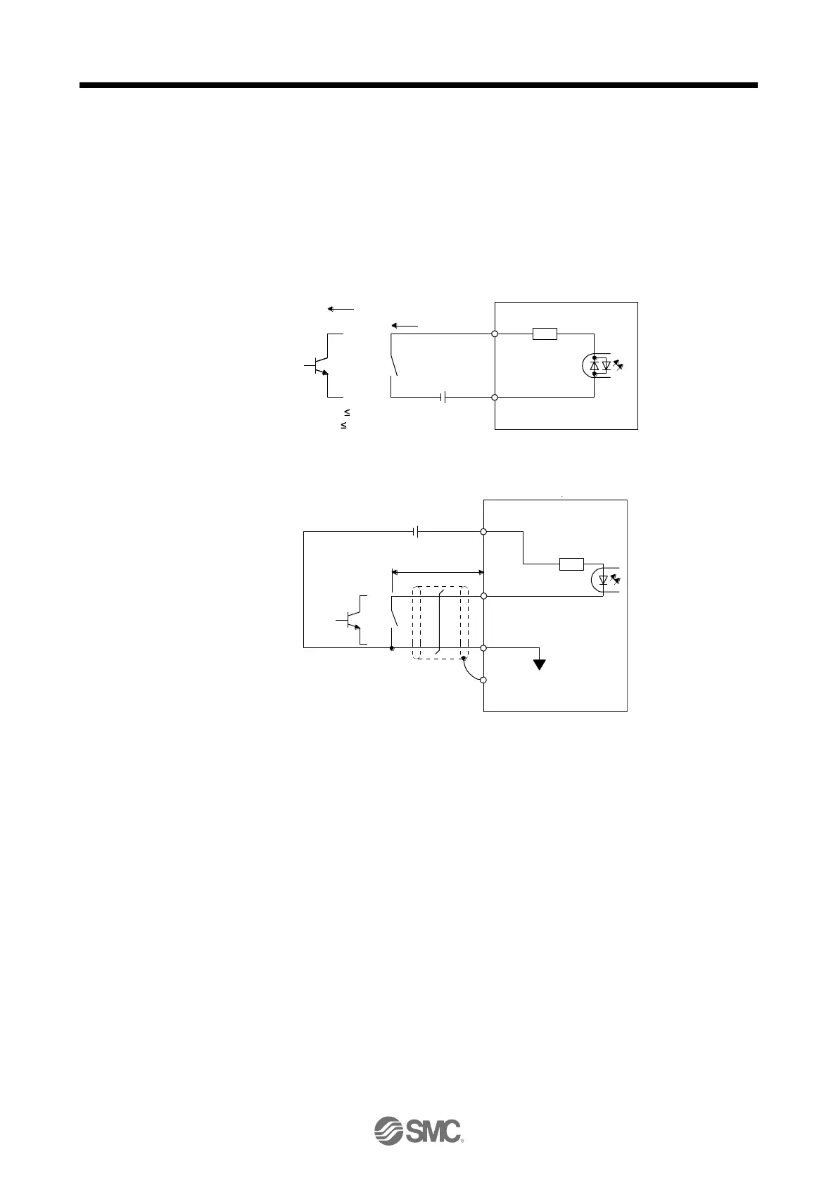
(1) Digital input interface DI-1
This is an input circuit whose photocoupler cathode side is the input terminal. Transmit signals from sink
(open-collector) type transistor output, relay switch, etc. The following is a connection diagram for sink
input. Refer to section 3.9.3 for source input.
Approximately
5 mA
TR
24 V DC ± 10%
500 mA
Switch
For transistor
EM2,
etc.
Servo amplifier
DICOM
V
CES
1.0 V
I
CEO
100 µA
Approximately
6.2 k Ω
The following is for when CN1-10 pin and CN1-35 pin are used as digital input interfaces.
Approx. 1.2 k
Ω
Servo amplifier
24 V DC ± 10%
300 mA
OPC
CN1-10, CN1-35
DOCOM
SD
10 m or less
VCES 1.0 V
ICEO 100 μA
Approx. 20 mA
Driver
Driver

Table of Contents

Questions and Answers:

Question and Answer IconNeed help?

Do you have a question about the SMC Networks LECSB2-T Series and is the answer not in the manual?

SMC Networks LECSB2-T Series Specifications

General IconGeneral
BrandSMC Networks
ModelLECSB2-T Series
CategoryDC Drives
LanguageEnglish