5. PARAMETERS
5 - 52
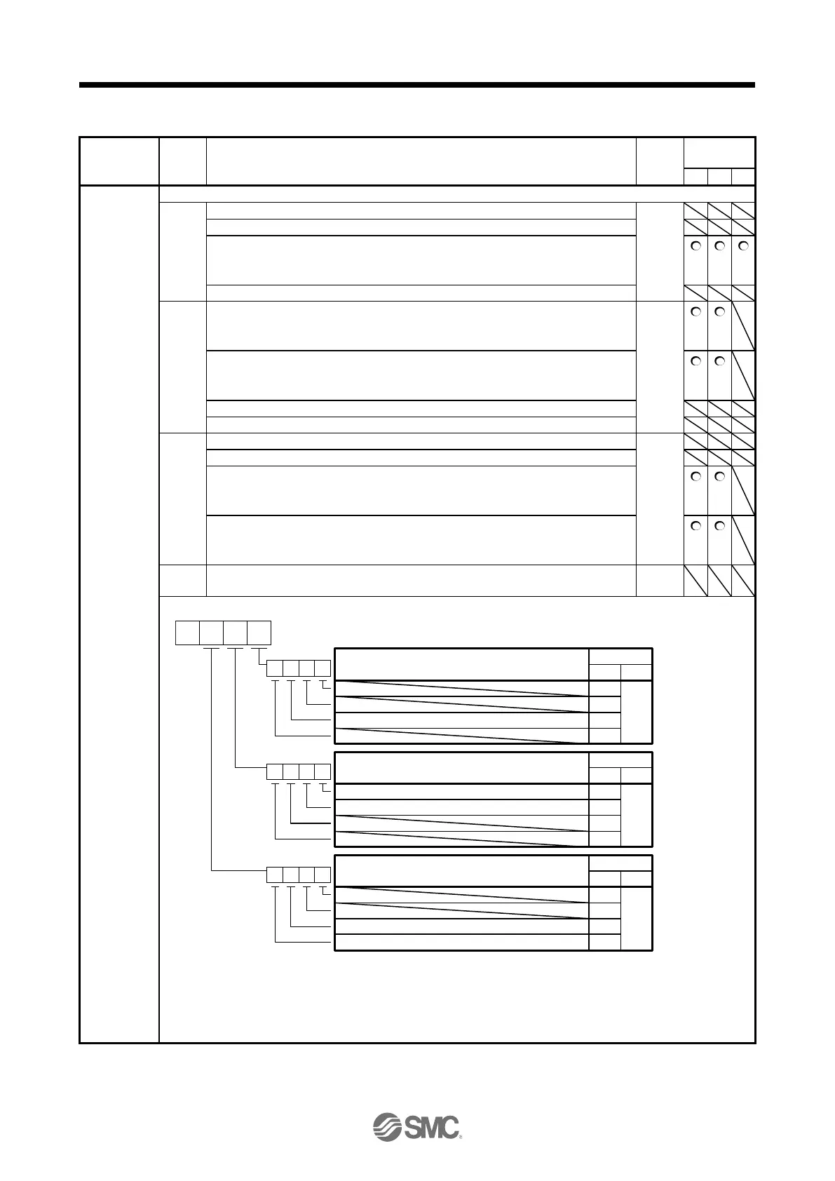
5.2.4 I/O setting parameters ([Pr. PD_ _ ])
PD01
*DIA1
Input signal
automatic on
selection 1
Select input devices to turn on them automatically.
_ _ _ x (BIN): For manufacturer setting
_ _ x _ (BIN): For manufacturer setting
_ x _ _ (BIN): SON (Servo-on)
0: Disabled (Use for an external input signal.)
1: Enabled (automatic on)
x _ _ _ (BIN): For manufacturer setting
_ _ _ x (BIN): PC (Proportional control)
0: Disabled (Use for an external input signal.)
1: Enabled (automatic on)
_ _ x _ (BIN): TL (External torque/external thrust limit selection)
0: Disabled (Use for an external input signal.)
1: Enabled (automatic on)
_ x _ _ (BIN): For manufacturer setting
x _ _ _ (BIN): For manufacturer setting
_ _ _ x (BIN): For manufacturer setting
_ _ x _ (BIN): For manufacturer setting
_ x _ _ (BIN): LSP (Forward rotation stroke end)
0: Disabled (Use for an external input signal.)
1: Enabled (automatic on)
x _ _ _ (BIN): LSN (Reverse rotation stroke end)
0: Disabled (Use for an external input signal.)
1: Enabled (automatic on)
Convert the setting value into hexadecimal as follows.
0
Initial value
BIN HEX
Signal name
0
0
0
0
0
SON (Servo-on)
0
Initial value
BIN HEX
Signal name
0
0
0
0
PC (Proportional control)
TL (External torque/external thrust limit selection)
0
BIN 0: Use for an external input signal.
BIN 1: Automatic on
Initial value
BIN HEX
Signal name
0
0
0
0
LSP (Forward rotation stroke end)
LSN (Reverse rotation stroke end)
Note EM2 (Forced stop 2) cannot be turned on automatically except in the positioning mode.
In other than the positioning mode, the electric actuator cannot operate unless the EM2 (forced stop 2) wiring is
performed, so an I / O connector or I / O cable is required.

 Loading...