EasyManuals Logo

SMC Networks LECSB2-T Series User Manual

SMC Networks LECSB2-T Series
945 pages
To Next Page IconTo Next Page
To Previous Page IconTo Previous Page
Page #567 background imageLoading...
Page #567 background image
16 - 67
16. POSITIONING MODE
16.3.7 External I/O signal display
POINT
The I/O signal settings can be changed using the I/O setting parameters [Pr.
PD04] to [Pr. PD28].
The on/off states of the digital I/O signals connected to the driver can be confirmed.
(1) Operation
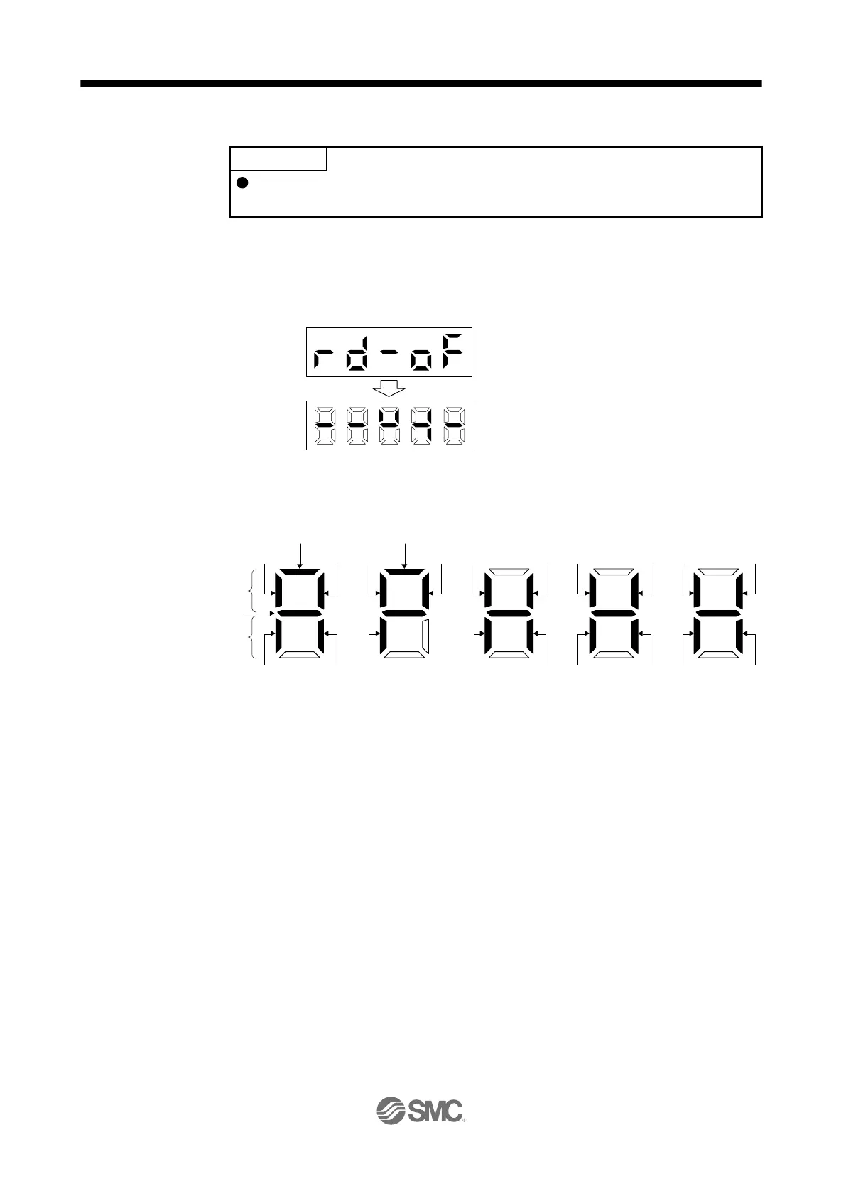
The display screen at power-on. Using the "MODE" button, display the diagnostic screen.
(2) Display definition
The 7-segment LED segments and CN1 connector pins correspond as shown below.
The LED segment corresponding to the pin is lit to indicate on, and is extinguished to indicate off.
For each pin signal in control modes, refer to section 2.2 (1).
Press the "UP" button twice.
…… External I/O signal display screen
Input signals
Output signals
Always lit
CN1-16 CN1-41
CN1-22CN1-48
CN1-19 CN1-15 CN1-44 CN1-43
CN1-23CN1-25 CN1-49CN1-24
Light on: on
Light off: off
CN1-18 CN1-17
CN1-33
CN1-45CN1-42
CN1-10 (Note 1)/
CN1-37 (Note 2)
CN1-35 (Note 1)/
CN1-38 (Note 2)
CN1-13CN1-14

Table of Contents

Questions and Answers:

Question and Answer IconNeed help?

Do you have a question about the SMC Networks LECSB2-T Series and is the answer not in the manual?

SMC Networks LECSB2-T Series Specifications

General IconGeneral
BrandSMC Networks
ModelLECSB2-T Series
CategoryDC Drives
LanguageEnglish