16.17.4 Parameter setting
In the indexer method, assign the following input device to CN1-18 pin with [Pr.
PD10].
CN1-18: MD1 (Operation mode selection 2)
Assign the following output devices to the CN1-22, CN1-23, and CN1-25 pins
with [Pr. PD23], [Pr. PD24], and [Pr. PD26].
CN1-22: CPO (Rough match)
CN1-23: ZP (Home position return completion)
CN1-25: MEND (Travel completion)
When using this servo in the indexer method, set [Pr. PA01] to "_ _ _ 8" (Positioning mode (indexer
method)). For the indexer method, the servo can be used by merely changing the basic setting parameters
([Pr. PA _ _ ]) and positioning control parameters ([Pr. PT _ _ ]) mainly.
As necessary, set other parameters.
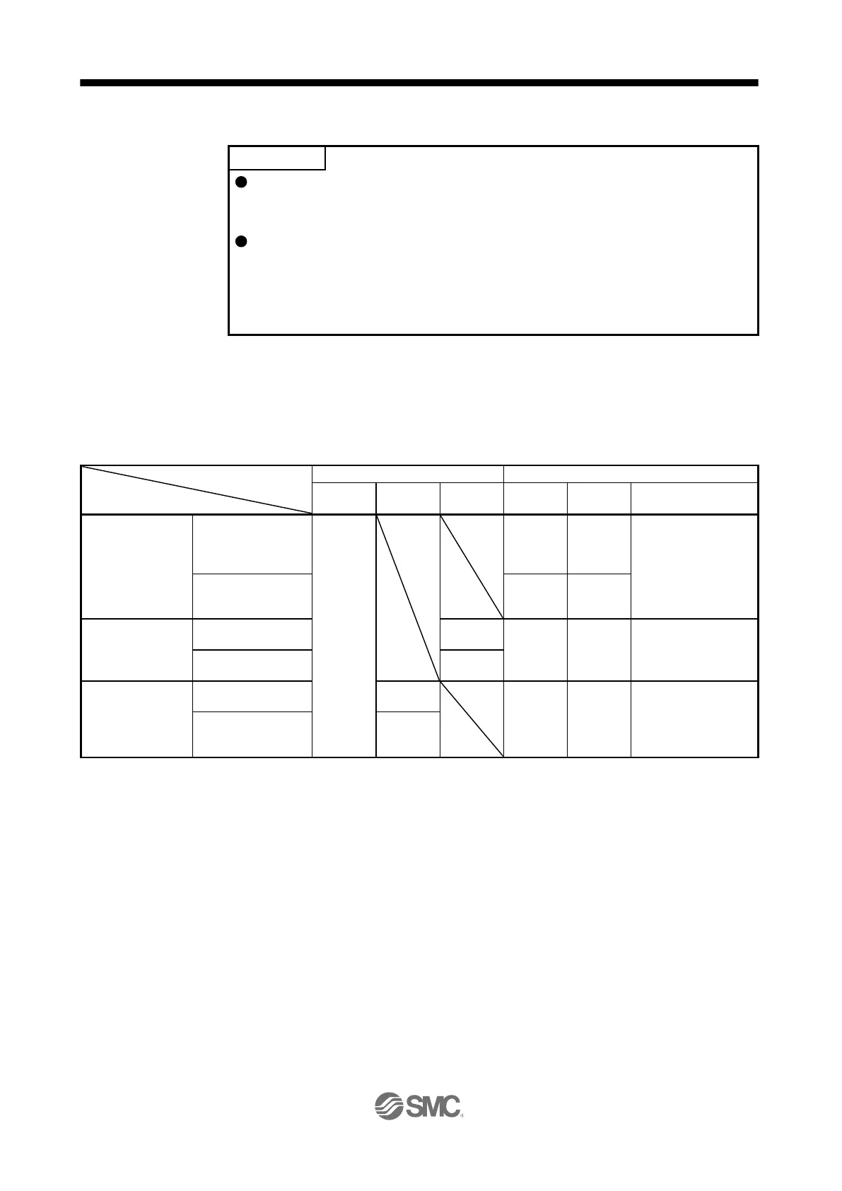
The following table shows [Pr. PA _ _ ] and [Pr. PT _ _ ] settings required for the indexer method.
Operation mode selection item
Operation mode
Automatic operation
mode 1
(Rotation direction
specifying indexer)
Set any next station
No. (Refer to section
6.2.2 (3).)
Automatic operation
mode 2 (Shortest
rotating indexer)
Home position
return mode
Dog type/Torque limit
changing dog type
Data set type/torque
limit changing data
set type
MD0: Operation mode selection 1, MD1: Operation mode selection 2, DI0 to DI7: Next station No. selection 1 to 8
Setting other than "_ _ _ 0" and "_ _ _ 2" will trigger [AL. 37 Parameter error].
In the indexer method, assign the following input device to CN1-18 pin with [Pr. PD10].
CN1-18: MD1 (Operation mode selection 2)

 Loading...