3. SIGNALS AND WIRING
3 - 15
3.3 Explanation of power supply system
3.3.1 Signal explanations
For the layout of connector and terminal block, refer to chapter 9 DIMENSIONS.
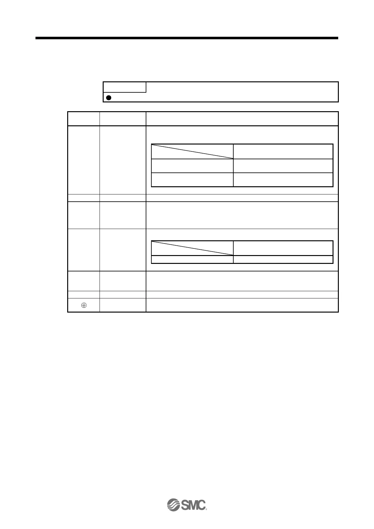
Connection target
(application)
Main circuit power
supply
Supply the following power to L1, L2, and L3. For 1-phase 200 V AC to 240 V AC,
connect the power supply to L1 and L3. Leave L2 open.
3-phase 200 V AC to 240 V AC,
50 Hz/60 Hz
1-phase 200 V AC to 240 V AC,
50 Hz/60 Hz
Connect P3 and P4. (factory-wired)
When using a driver built-in regenerative resistor, connect P+ and D. (factory-wired)
When using a regenerative option, disconnect P+ and D, and connect the
regenerative option to P+ and C.
Refer to section 11.2 for details.
Control circuit
power supply
Supply the following power to L11 and L21.
1-phase 200 V AC to 240 V AC
Connect the driver power output (U/V/W) to the servo motor power input (U/V/W)
directly. Do not let a magnetic contactor, etc. intervene. Otherwise, it may cause a
malfunction.
Do not connect to the driver.
Connect it to the grounding terminal of the servo motor and to the protective earth
(PE) of the cabinet for grounding.

 Loading...