17.7.3 Point table
Point table method when using the pushing operation, set each value of the point table using the setup
software (MR Configurator2
TM
) or the operation unit.
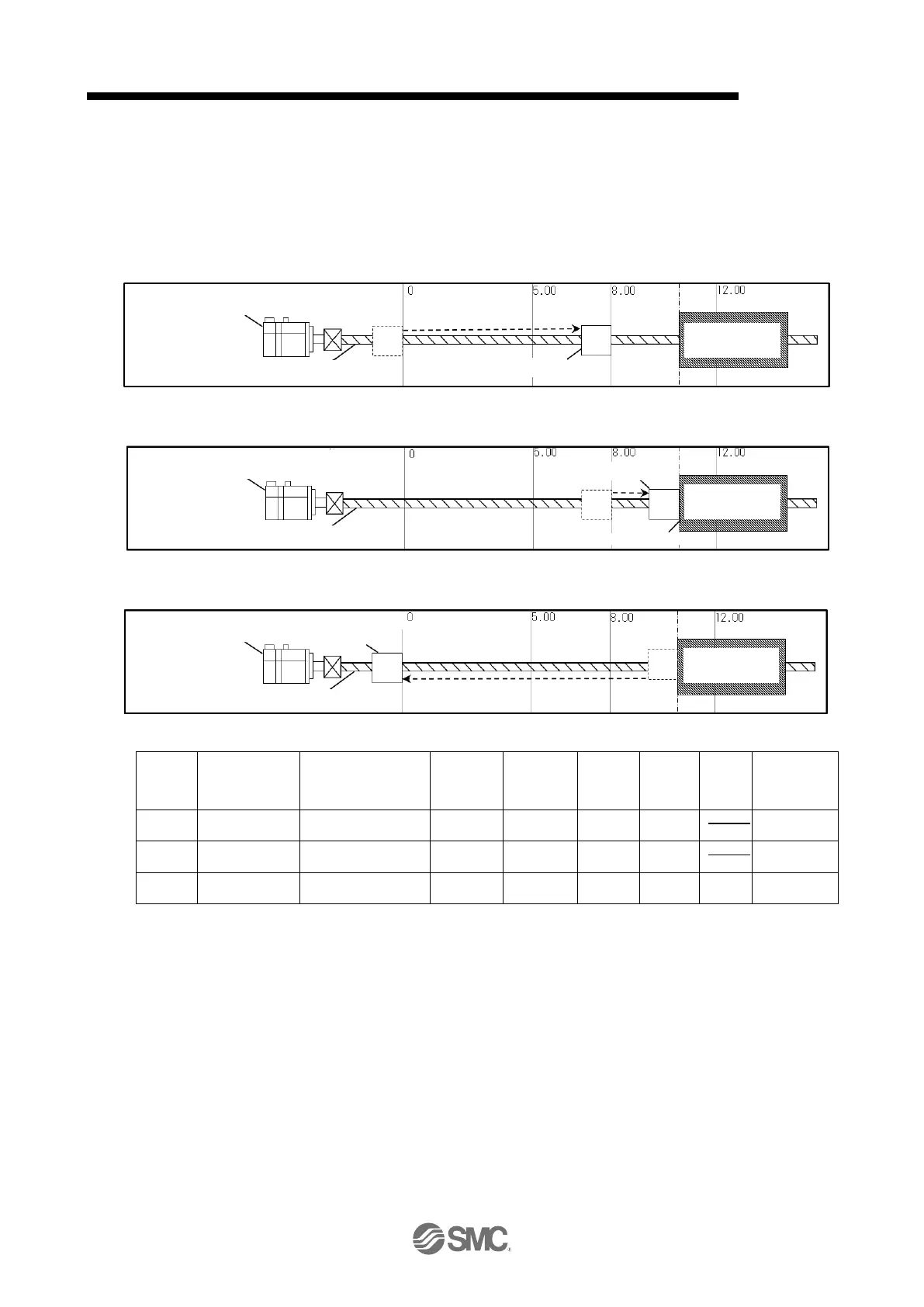
The following describes an example of pushing operation divided into the following three steps.
<STEP1> In positioning operation, move from Positioning start position to Pushing start position
(operation of point table 1)
<STEP2> In the pushing operation, perform the pushing operation to the pushing object (operation of
point table 2).
<STEP3> Return to Positioning start position in positioning operation
(operation of point table 3)
Assign a point table for each of the above STEPs.
Note1:Set the auxiliary function to "1", "3", "8" or "9" and perform continuous operation when dwell = 0.
At this time, the acceleration time constant and deceleration time constant data selected when
starting position data are valid The acceleration time constant and deceleration time constant of
the following point tables are disabled.
Note2:When performing the pushing operation, always set the dwell of the point table data immediately
before the pushing operation to “0”.
If you set a value other than “0”, [AL7F.4 Pushing start error] will occur.
Note3:When "0", "2", "16" or "18" is set for the auxiliary function, the dwell of this point table No is
disabled.
Note4:When the point table number including the pushing operation is started, no M code is output.
Note5:If a value other than "16" or "18" is set for the auxiliary function, the pushing torque of this point
table No will be disabled.
The positioning operation using the point table number selected when ST1 (start signal) is turned on, and
the pushing operation using consecutive point table numbers are performed. After reaching the pushing
torque, confirm that INP is turned on, and select and start the next point table. At this time, the pushing
operation is continued (the pushing torque is continued) until ST1 is entered.

 Loading...