1. FUNCTIONS AND CONFIGURATION
1 - 14
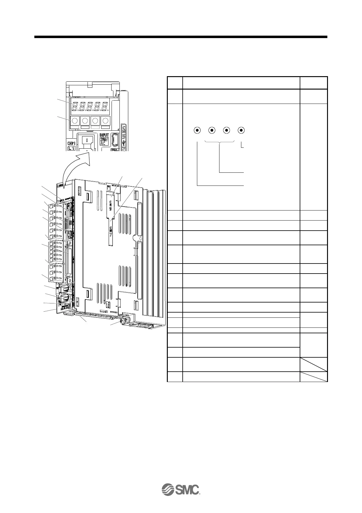
1.7 Structure
1.7.1 Parts identification
(1) LECSB2-T□
Inside of the display cover
MODE UP DOWN SET
(1)
(2)
(4)
(12)
(14)
(13)
(17)
Side
(9)
(5)
(6)
(7)
(16)
(15)
(8)
(3)
(18)
(10) (11)
(19)
Display
The 5-digit, 7-segment LED shows the servo status and the
alarm number.
Operation section
Used to perform status display, diagnostic, alarm, and
parameter setting operations. Push the "MODE" and "SET"
buttons at the same time for 3 s or more to switch to the
one-touch tuning mode.
Used to set data.
Push this button
together with the "MODE"
button for 3 s or more
to switch to the
one-touch tuning mode.
MODE UP DOWN SET
Used to change the
display or data in each
mode.
Used to change the mode.
Push this button
together with the "SET"
button for 3 s or more
to switch to the
one-touch tuning mode.
USB communication connector (CN5)
Connect with the personal computer.
Analog monitor connector (CN6)
Outputs the analog monitor.
RS-422/RS-485 communication connector (CN3)
Connect with the RS-422/RS-485 communication controller,
etc.
STO input signal connector (CN8)
Used to connect the MR-J3-D05 (manufactured by
Mitsubishi Electric Corporation) safety logic unit and external
safety relay.
I/O signal connector (CN1)
Used to connect digital I/O signals.
Encoder connector (CN2)
Used to connect the servo motor encoder or external
encoder.
Battery connector (CN4)
Used to connect the battery for absolute position data
backup.
Battery holder
Install the battery for absolute position data backup.
Protective earth (PE) terminal
Main circuit power connector (CNP1)
Connect the input power supply.
Control circuit power connector (CNP2)
Connect the control circuit power supply and regenerative
option.
Servo motor power output connector (CNP3)
Connect the servo motor.
Charge lamp
When the main circuit is charged, this will light up. While this
lamp is lit, do not reconnect the cables.
External encoder connector (CN2L)
Refer to table 1.1 for the compatible external encoders.

 Loading...