EasyManuals Logo
Home>SMC Networks>DC Drives>LECSB2-T Series

SMC Networks LECSB2-T Series User Manual

SMC Networks LECSB2-T Series
945 pages
To Next Page IconTo Next Page
To Previous Page IconTo Previous Page
Page #838 background imageLoading...
Page #838 background image
16 - 338
16. POSITIONING MODE
16.28.5 Output signal pin on/off (output signal (DO) forced output)
In the test operation mode, the output signal pins can be turned on/off regardless of the servo status.
Disable the external input signals in advance with command [9] [0].
(1) Selecting the output signal (DO) forced output of the test operation mode
Transmit command + [8] [B] + data No. [0] [0] + data "0004" to select the output signal (DO) forced
output.
(2) External output signal on/off
Transmit the following communication commands.
Command
Data No.
Setting data
[9] [2]
[A] [0], [A] [1]
See below.
Bit
CN1 connector pin
CN10 connector pin
Bit
CN1 connector pin
CN10 connector pin
0
49
22
16
1
24
23
17
2
23
24
18
3
25
25
19
4
22
38
20
5
48
39
21
6
33
40
22
7
13
41
23
8
14
42
24
9
43
25
10
44
26
11
45
27
12
46
28
13
47
29
14
48
30
15
49
31
(3) Output signal (DO) forced output
To stop the output signal (DO) forced output, transmit command [8] [B] + data No. [0] [0] + data. Before
switching from the test operation mode to the normal operation mode, turn off the driver once.
Command
Data No.
Transmission
data
Selection of test operation mode
[8] [B]
[0] [0]
0000
Test operation mode canceled
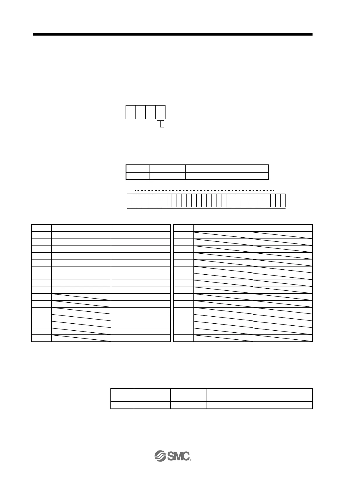
0 0 4
Selection of test operation mode
4: Output signal (DO) forced output
0
b31 b1b0
1: On
0: Off
Command of each bit is transmitted to the master station as hexadecimal data.

Table of Contents

Questions and Answers:

Question and Answer IconNeed help?

Do you have a question about the SMC Networks LECSB2-T Series and is the answer not in the manual?

SMC Networks LECSB2-T Series Specifications

General IconGeneral
BrandSMC Networks
ModelLECSB2-T Series
CategoryDC Drives
LanguageEnglish