APPENDIX
App. - 25
App .11 Recommended parameter values for each actuator
Please change the parameter values according to the customer application. See section 5, section 16
of the “LECSB2-T□ Operation Manual” for details.
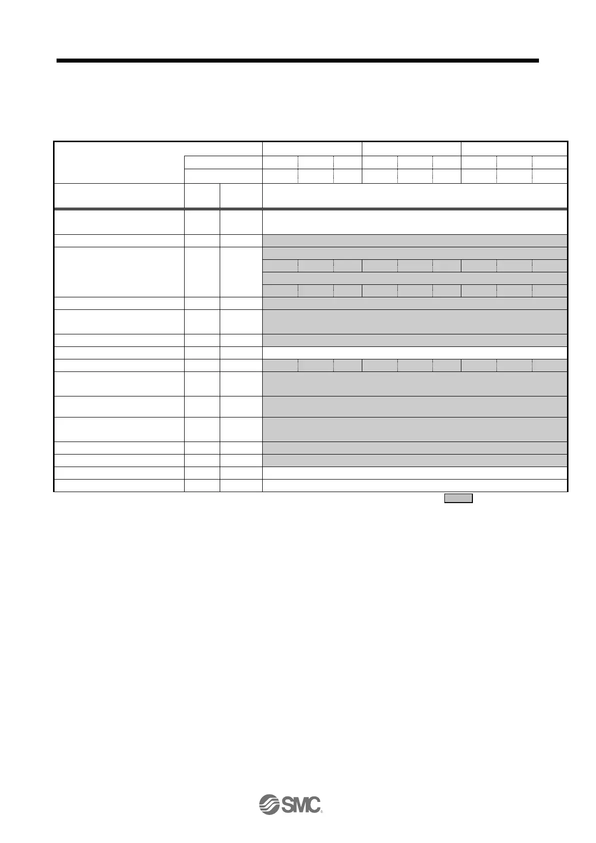
Recommended Parameter Values [LEF]
Number of command input pulses
per revolution
*3.
Electronic gear numerator *3.
Electronic gear denominator *3.
2001 (J3 electronic gear setting value compatibility mode)
Feel length multiplication (STM)
(Multiplier)
0000 ((<1000 stroke)/0001 (>1000 stroke)
Home position return type
Home position return direction
Home position return Speed (rpm)
Home position return position data
(μm)
-2000 (<1000 stroke)/-200 (>1000 stroke)
Stopper type home position return
stopper time (msec)
Stopper type home position return
torque limit value (%)
0000 (Non)/0002 (LEC-MR-RB-032)
Rotation direction selection *4
1 (+:Counter motors side)
Load to motor inertia moment ratio
*1. Parameter is set to the recommended value. Please set parameter according to customer application.
*2. Mechanical resonance may occur depending on the shape or mounting orientation of the work piece.
Please change this parameter during initial configuration.
(Parameter initial configuration ⇒ Set the recommended parameter value ⇒ Operation start)
*3. Other than positioning mode: Actuator travel distance at 10 [μm/pulse] per pulse.
Positioning Mode: Minimum actuator travel distance of 1[μm].
*4. When the motor mounting position is right side parallel (LEFS*R) or left side parallel (LEFS*L), the
rotation direction selection is 0(+: Counter motors side).

 Loading...