EasyManuals Logo

SMC Networks LECSB2-T Series User Manual

SMC Networks LECSB2-T Series
945 pages
To Next Page IconTo Next Page
To Previous Page IconTo Previous Page
Page #433 background imageLoading...
Page #433 background image
12. ABSOLUTE POSITION DETECTION SYSTEM
12 - 21
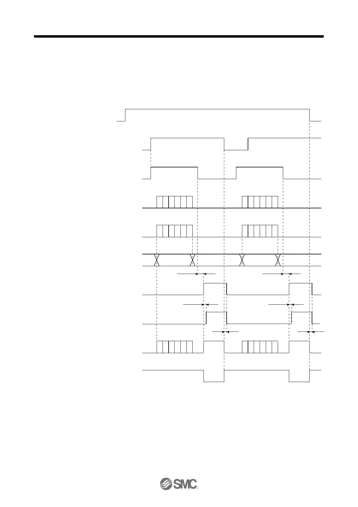
12.6.4 Use of servo motor with an electromagnetic lock
The timing charts at power on/off and SON on/off are given below.
Preset [Pr. PD23] to [Pr. PD26], [Pr. PD28], and [Pr. PD47] of the driver to enable MBR. When MBR is set
for the CN1-23 pin, turning ABSM on will change the CN1-23 pin to ABSB1 (ABS transmission data bit 1).
Therefore, configure an external sequence to generate the electromagnetic lock torque as soon as ABSM
and MBR turn off.
OFF
ON
OFF
ON
OFF
ON
OFF
ON
OFF
ON
OFF
ON
OFF
ON
OFF
ON
OFF
ON
95 ms
5 ms
Tb
95 ms
5 ms
Tb
Power
supply
SON
ABSM
ABSR
ABST
ABSB0
ABSB1
Base circuit
RD
MBR
Electromagnetic
brake torque
During transmission
of ABS
During transmission
of ABS
Absolute position
data
Absolute position
data

Table of Contents

Questions and Answers:

Question and Answer IconNeed help?

Do you have a question about the SMC Networks LECSB2-T Series and is the answer not in the manual?

SMC Networks LECSB2-T Series Specifications

General IconGeneral
BrandSMC Networks
ModelLECSB2-T Series
CategoryDC Drives
LanguageEnglish