14. COMMUNICATION FUNCTION
14 - 12
14.4 Command and data No. list
Even if a command or data No. is the same between different model drivers, its
description may differ.
14.4.1 Reading command
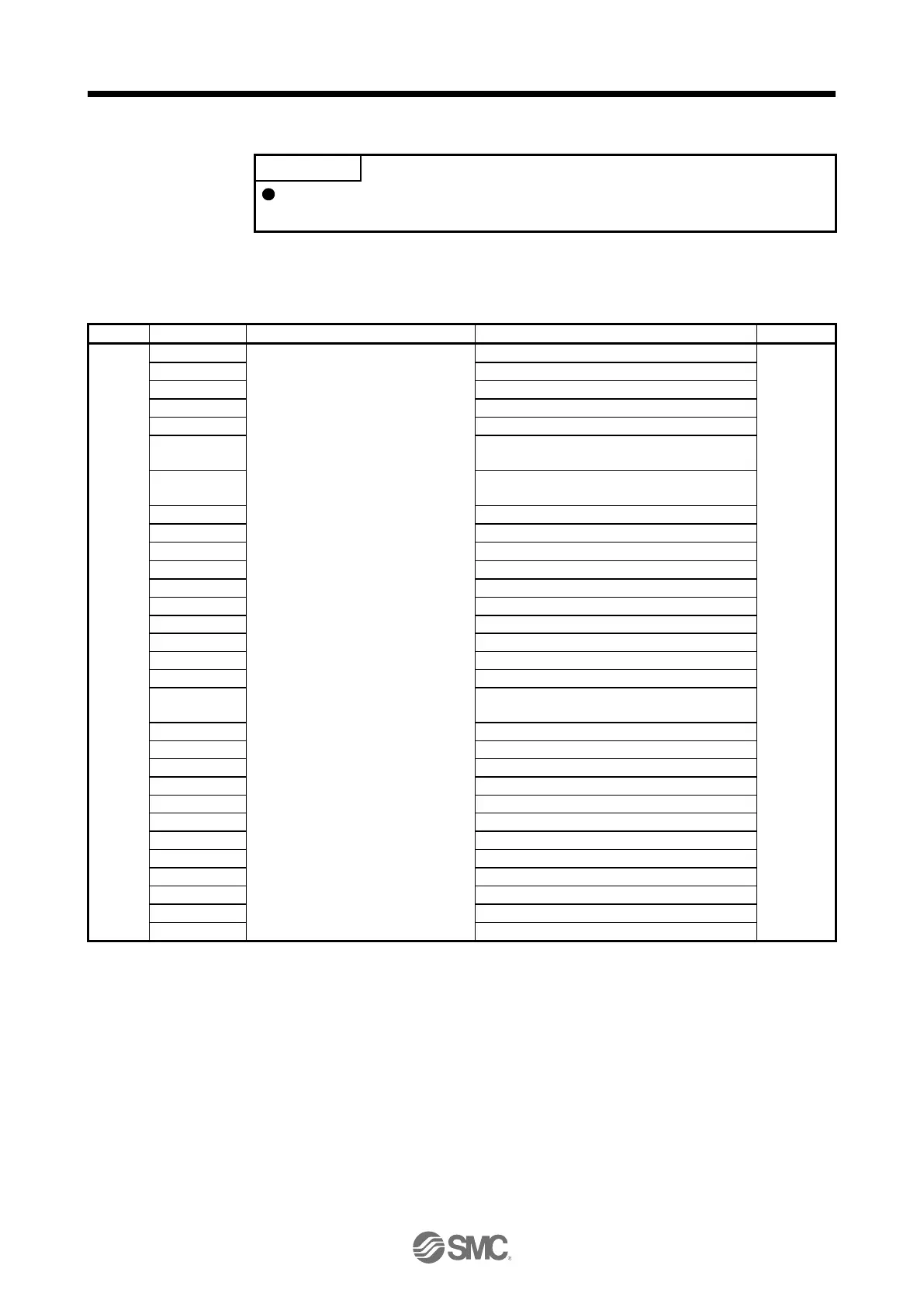
(1) Status display (command [0] [1])
Status display symbol and unit
Cumulative feedback pulses
Cumulative command pulses
Analog speed command voltage
Analog speed limit voltage
Analog torque limit voltage
Analog torque command voltage
Position within one-revolution
Load to motor inertia ratio
Load-side cumulative feedback pulses
Load-side encoder information 1
Z-phase counter
Load-side encoder information 2
Temperature of motor thermistor
Motor-side cumu. feedback pulses (before gear)
Motor-side/load-side position deviation
Motor-side/load-side speed deviation
Internal temperature of encoder
Oscillation detection frequency
Number of tough operations
Unit total power consumption

 Loading...