4. STARTUP
4 - 29
4.5.7 External I/O signal display
The I/O signal settings can be changed using the I/O setting parameters [Pr.
PD23] to [Pr. PD26], [Pr. PD28], and [Pr. PD47].
The on/off states of the digital I/O signals connected to the driver can be confirmed.
(1) Operation
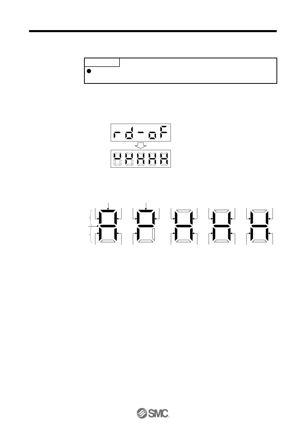
Call the display screen shown after power-on. Using the "MODE" button, show the diagnostic screen.
Press "UP" twice.
……
External I/O signal display screen
(2) Display definition
The 7-segment LED segments and CN1 connector pins correspond as shown below.
Input signals
Output signals
Always lit
Light on: on
Light off: off
CN1-16 CN1-41
CN1-22CN1-48
CN1-19 CN1-15 CN1-44 CN1-43
CN1-23CN1-25 CN1-49CN1-24
CN1-18 CN1-17
CN1-33
CN1-45
CN1-10 (Note 1)/
CN1-37 (Note 2)
CN1-35 (Note 1)/
CN1-38 (Note 2)
CN1-42
CN1-13
(Note 1)
CN1-14
(Note 1)
The LED segment corresponding to the pin is lit to indicate on, and is extinguished to indicate off.
The signals corresponding to the pins in the respective control modes are indicated below.
 Loading...