EasyManuals Logo

SMC Networks LECSB2-T Series User Manual

SMC Networks LECSB2-T Series
945 pages
To Next Page IconTo Next Page
To Previous Page IconTo Previous Page
Page #143 background imageLoading...
Page #143 background image
4. STARTUP
4 - 30
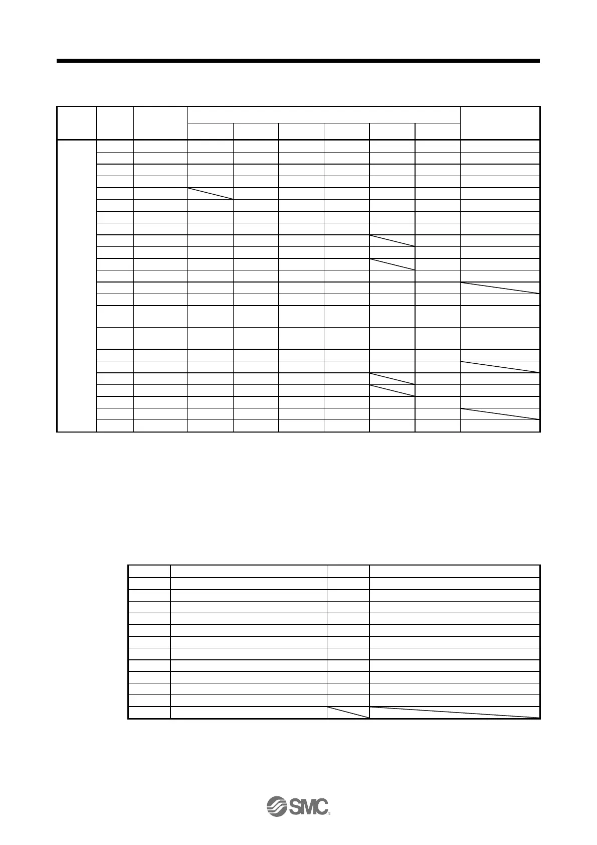
(a) Control modes and I/O signals
Connector
Pin No.
Signal
input/output
(Note 1) I/O
(Note 2) Symbols of I/O signals in control modes
Related parameter
P
P/S
S
S/T
T
T/P
10
I
PP
PP/-
(Note 5)
(Note 5)
(Note 5)
-/PP
PD43/PD44
13
O
(Note 3)
(Note 3)
(Note 3)
(Note 3)
(Note 3)
(Note 3)
PD47
14
O
(Note 3)
(Note 3)
(Note 3)
(Note 3)
(Note 3)
(Note 3)
PD47
15
I
SON
SON
SON
SON
SON
SON
PD03/PD04
16
I
-/SP2
SP2
SP2/SP2
SP2
SP2/-
PD05/PD06
17
I
PC
PC/ST1
ST1
ST1/RS2
RS2
RS2/PC
PD07/PD08
18
I
TL
TL/ST2
ST2
ST2/RS1
RS1
RS1/TL
PD09/PD10
19
I
RES
RES
RES
RES
RES
RES
PD11/PD12
22
O
INP
INP/SA
SA
SA/-
-/INP
PD23
23
O
ZSP
ZSP
ZSP
ZSP
ZSP
ZSP
PD24
CN1
24
O
INP
INP/SA
SA
SA/-
-/INP
PD25
25
O
TLC
TLC
TLC
TLC/VLC
VLC
VLC/TLC
PD26
33
O
OP
OP
OP
OP
OP
OP
35
I
NP
NP/-
(Note 5)
(Note 5)
(Note 5)
-/NP
PD45/PD46
37
(Note 7)
I
PP2
PP2/-
(Note 6)
(Note 6)
(Note 6)
-/PP2
PD43/PD44
38
(Note 7)
I
NP2
NP2/-
(Note 6)
(Note 6)
(Note 6)
-/NP2
PD45/PD46
41
I
CR
CR/SP1
SP1
SP1/SP1
SP1
SP1/CR
PD13/PD14
42
I
EM2
EM2
EM2
EM2
EM2
EM2
43
I
LSP
LSP
LSP
LSP/-
-/LSP
PD17/PD18
44
I
LSN
LSN
LSN
LSN/-
-/LSN
PD19/PD20
45
I
LOP
LOP
LOP
LOP
LOP
LOP
PD21/PD22
48
O
ALM
ALM
ALM
ALM
ALM
ALM
49
O
RD
RD
RD
RD
RD
RD
PD28
Note 1.
I: input signal, O: output signal
2.
P: position control mode, S: speed control mode, T: torque control mode
P/S: position/speed control switching mode, S/T: speed/torque control switching mode, T/P: torque/position switching mode
3.
Output devices are not assigned by default. Assign the output devices with [Pr. PD47] as necessary.
5.
This is available as an input device of sink interface. Input devices are not assigned by default. Assign the input devices with
[Pr. PD43] to [Pr. PD46] as necessary. Supply + of 24 V DC to CN1-12 pin.
6.
This is available as an input device of source interface. Input devices are not assigned by default. Assign the input devices
with [Pr. PD43] to [Pr. PD46] as necessary.
(b) Symbol and signal names
Symbol
Application
Symbol
Application
SON
Servo-on
RES
Reset
LSP
Forward rotation stroke end
EM2
Forced stop 2
LSN
Reverse rotation stroke end
LOP
Control switching
CR
Clear
TLC
Limiting torque
SP1
Speed selection 1
VLC
Limiting speed
SP2
Speed selection 2
RD
Ready
PC
Proportion control
ZSP
Zero speed detection
ST1
Forward rotation start
INP
In-position
ST2
Reverse rotation start
SA
Speed reached
RS1
Forward rotation selection
ALM
Malfunction
RS2
Reverse rotation selection
OP
Encoder Z-phase pulse (open collector)
TL
External torque limit selection

Table of Contents

Questions and Answers:

Question and Answer IconNeed help?

Do you have a question about the SMC Networks LECSB2-T Series and is the answer not in the manual?

SMC Networks LECSB2-T Series Specifications

General IconGeneral
BrandSMC Networks
ModelLECSB2-T Series
CategoryDC Drives
LanguageEnglish