16.4.5 Point table setting
Set the data for operation to the point table. The following shows the items to be set.
Set the position data for movement.
Set the command speed of the servo motor for execution of positioning.
Acceleration
time constant
Set the acceleration time constant.
Deceleration
time constant
Set the deceleration time constant.
Set the waiting time when performing automatic continuous operation.
Set when performing automatic continuous operation.
Outputs the first digit and the second digit of the M code in 4-bit binary
respectively.
Refer to section 4.2.2 for details of the point table.
16.4.6 Actual operation
Start actual operation after confirmation of normal operation by test operation and completion of the
corresponding parameter settings.
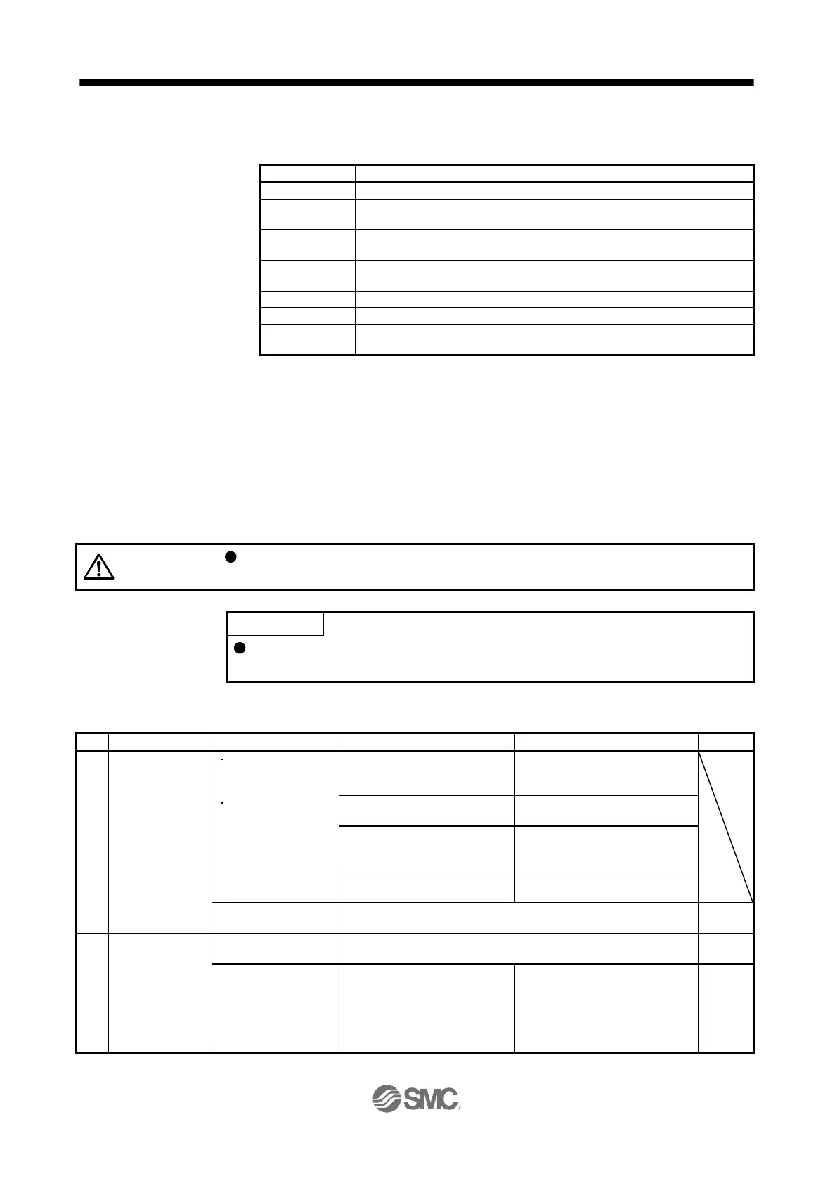
16.4.7 Troubleshooting at start-up
Never make a drastic adjustment or change to the parameter values as doing so
will make the operation unstable.
Using Setup software (MR Configurator2
TM
), you can refer to the reason for
rotation failure, etc.
The following faults may occur at start-up. If any of such faults occurs, take the corresponding action.
The 7-segment LED
display does not turn
on.
The 7-segment LED
display flickers.
Not improved even if CN1, CN2,
and CN3 connectors are
disconnected.
1. Power supply voltage fault
2. The driver is malfunctioning.
Improved when CN1 connector is
disconnected.
Power supply of CN1 cabling is
shorted.
Improved when CN2 connector is
disconnected.
1. Power supply of encoder
cabling is shorted.
2. Encoder is malfunctioning.
Improved when CN3 connector is
disconnected.
Power supply of CN3 cabling is
shorted.
Refer to chapter 8 and remove the cause.
Switch on SON
(Servo-on).
Refer to chapter 8 and remove the cause.
Servo motor shaft is
not servo-locked.
(Servo motor shaft is
free.)
1. Check the display to see if the
driver is ready to operate.
2. Check the external I/O signal
indication (section 3.1.7 or
3.2.7) to see if SON (Servo-
on) is on.
1. SON (Servo-on) is not input.
(wiring mistake)
2. 24 V DC power is not supplied
to DICOM.
Section
3.1.7
Section
3.2.7

 Loading...