PD03
*DI1L
Input device
selection 1L
Any input device can be assigned to the CN1-15 pin.
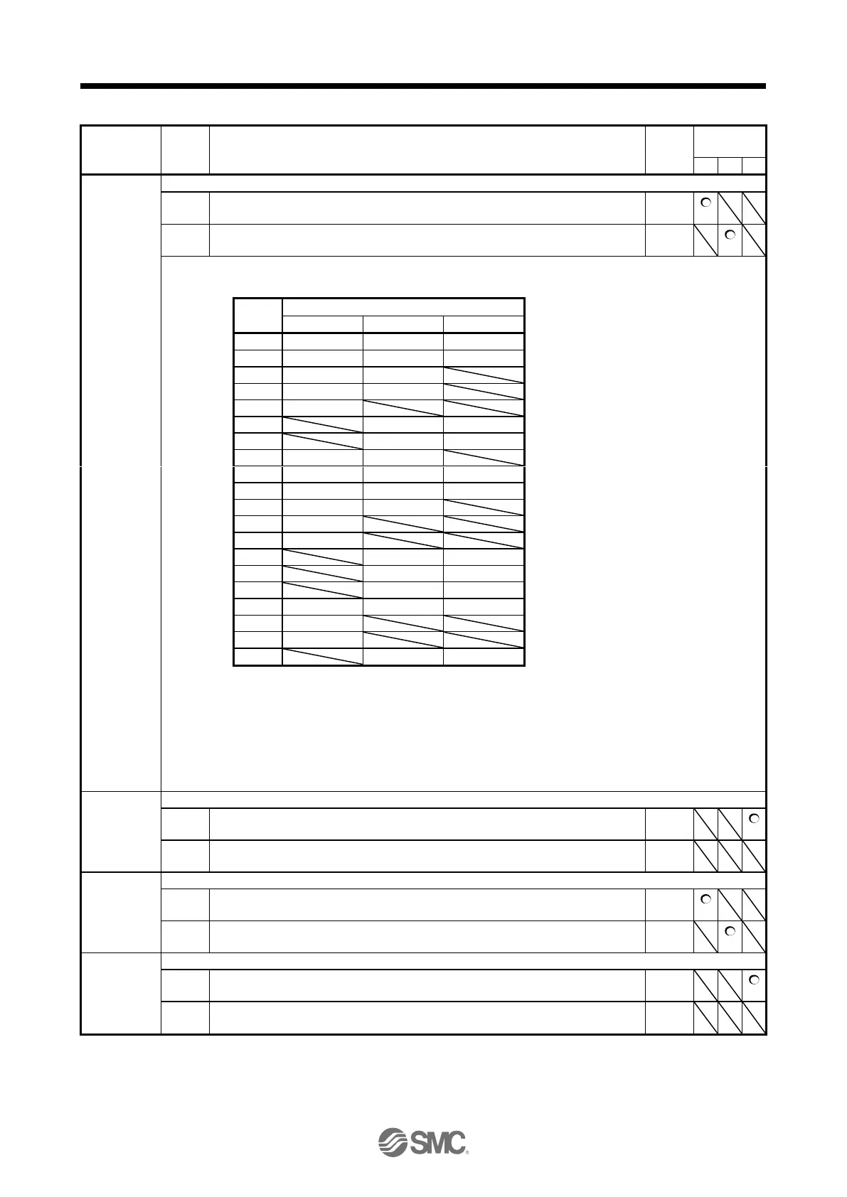
Position control mode - Device selection
Refer to table 5.10.
Speed control mode - Device selection
Refer to table 5.10.
Table 5.10 Selectable input devices
P: Position control mode, S: Speed control mode, T: Torque control mode
The diagonal lines indicate manufacturer settings. Never change the setting.
When assigning LOP (Control switching), assign it to the same pin in all control modes.
In the torque control mode, this device cannot be used during normal operation. Also, when
the magnetic pole detection in the torque control mode is completed, this signal will be
disabled.
PD04
*DI1H
Input device
selection 1H
Any input device can be assigned to the CN1-15 pin.
Torque control mode - Device selection
Refer to table 5.10 in [Pr. PD03] for settings.
PD05
*DI2L
Input device
selection 2L
Any input device can be assigned to the CN1-16 pin.
Position control mode - Device selection
Refer to table 5.10 in [Pr. PD03] for settings.
Speed control mode - Device selection
Refer to table 5.10 for settings.
PD06
*DI2H
Input device
selection 2H
Any input device can be assigned to the CN1-16 pin.
Torque control mode - Device selection
Refer to table 5.10 in [Pr. PD03] for settings.

 Loading...