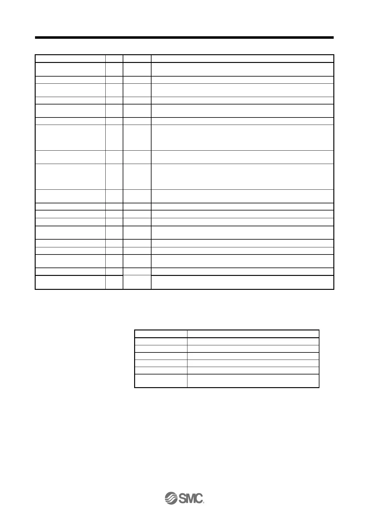
Load to motor inertia ratio
The estimated ratio of the load inertia moment to the servo motor shaft inertia
moment is displayed.
The voltage of main circuit converter (between P+ and N-) is displayed.
Internal temperature of
encoder
Inside temperature of encoder detected by the encoder is displayed.
Settling time is displayed. When it exceeds 1000 ms, "1000" will be displayed.
Oscillation detection
frequency
Frequency at the time of oscillation detection is displayed.
Number of tough operations
The number of tough drive functions activated is displayed.
Unit power consumption 1
(increment of 1 W)
Unit power consumption is displayed by increment of 1 W. Positive value
indicate power running, and negative value indicate regeneration. The values in
excess of ±99999 can be counted. However, the counter shows only the lower
five digits of the actual value since the driver display is five digits.
Unit power consumption 2
(increment of 1 kW)
Unit power consumption is displayed by increment of 1 kW. Positive value
indicate power running, and negative value indicate regeneration.
Unit total power consumption
1 (increment of 1 Wh)
Unit total power consumption is displayed by increment of 1 Wh. Positive value
is cumulated during power running and negative value during regeneration. The
values in excess of ±99999 can be counted. However, the counter shows only
the lower five digits of the actual value since the driver display is five digits.
Unit total power consumption
2 (increment of 100 kWh)
Unit total power consumption is displayed by increment of 100 kWh. Positive
value is cumulated during power running and negative value during regeneration.
The Z-phase counter is displayed in the encoder pulse unit.
The Z-phase counter is displayed by increments of 100000 pulses.
The servo motor electrical angle is displayed.
The servo motor electrical angle is displayed by increments of 100000 pulses.
(4) Changing the status display screen
The status display item of the driver display shown at power-on can be changed by changing [Pr. PC36]
settings. The item displayed in the initial status changes with the control mode as follows.
Cumulative feedback pulses
Cumulative feedback pulses/servo motor speed
Servo motor speed/analog torque command voltage
Analog torque command voltage
Analog torque command voltage/cumulative feedback
pulses
 Loading...