EasyManuals Logo

SMC Networks LECSB2-T Series User Manual

SMC Networks LECSB2-T Series
945 pages
To Next Page IconTo Next Page
To Previous Page IconTo Previous Page
Page #278 background imageLoading...
Page #278 background image
7. SPECIAL ADJUSTMENT FUNCTIONS
7 - 30
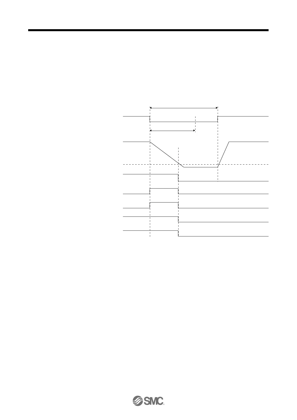
(2) Instantaneous power failure time of the control circuit power supply < [Pr. PF25 SEMI-F47 function -
Instantaneous power failure detection time]
Operation status differs depending on how bus voltage decrease.
(a) When the bus voltage decrease lower than undervoltage level within the instantaneous power failure
time of the control circuit power supply
[AL. 10 Undervoltage] occurs when the bus voltage decrease lower than undervoltage level
regardless of the enabled instantaneous power failure tough drive.
ON (energization)
OFF (power failure)
[Pr. PF25]
Instantaneous power failure time of the control circuit power supply
ON
OFF
ON
OFF
ON
OFF
ON
OFF
ON
OFF
Control circuit
power supply
Bus voltage
Undervoltage level
(Note)
ALM
(Malfunction)
MTTR
(During tough drive)
MBR
(Electromagnetic
brake interlock)
Base circuit
WNG
(Warning)
Note.
Refer to table 7.1 for the undervoltage level.

Table of Contents

Questions and Answers:

Question and Answer IconNeed help?

Do you have a question about the SMC Networks LECSB2-T Series and is the answer not in the manual?

SMC Networks LECSB2-T Series Specifications

General IconGeneral
BrandSMC Networks
ModelLECSB2-T Series
CategoryDC Drives
LanguageEnglish