8. TROUBLESHOOTING
8 - 23
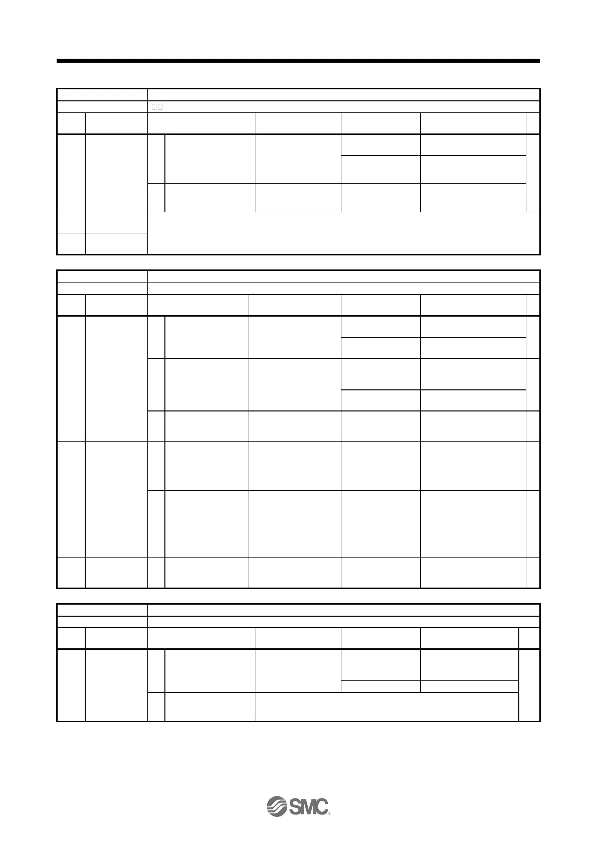
Name: Memory error 3 (Flash-ROM)
A part (Flash-ROM) in the driver is failure.
The Flash-ROM is
malfunctioning.
Disconnect the cables
except for the control
circuit power supply,
and then check the
repeatability.
Something near the
device caused it.
Check the noise,
ambient temperature,
etc.
There is a problem in
the surrounding.
Take countermeasures
against its cause.
Check it with the check method for [AL. 19.1].
Name: Servo motor combination error
・
The combination of driver and servo motor is incorrect.
Servo motor
combination
error 1
The driver and the
servo motor was
connected incorrectly.
Check the model name
of the servo motor and
corresponding driver.
The combination is
incorrect.
Use them in the correct
combination.
The combination is
correct.
The setting of [Pr.
PA01] is not
corresponding to
the connected servo
motor.
Check the [Pr. PA01]
setting.
Rotary servo motor: "0"
The combination is
incorrect.
Set [Pr. PA01] correctly.
When using a linear
servo motor, also check (3).
The combination is
correct.
An encoder is
malfunctioning.
Replace the servo motor,
and then check the
repeatability.
Servo motor
control mode
combination
error
The setting of [Pr.
PA01] is not
corresponding to
the connected servo
motor
Check the [Pr. PA01]
setting.
Rotary servo motor: "0"
The combination is
incorrect.
Set [Pr. PA01] correctly.
When the fully closed
loop control mode is
selected, encoders of
the servo motor side
and the machine side
are connected
reversely.
Check the connection
destination of the
encoder.
The connection
destination of the
encoder is incorrect
Servo motor
combination
error 2
Thedriver is
malfunctioning.
Replace the driver, and
then check the
repeatability.
An alarm occurred in the converter unit during the servo-on.
The protection
coordination cable is
not correctly connected
Check the protection
coordination cable
connection.
Connect it correctly.
It is connected. Check
(2).
An alarm occurred in
the converter unit
during the servo-on.
Check the alarm of the converter unit, and take the action following the
remedies for alarms of the converter unit.
 Loading...