3. SIGNALS AND WIRING
3 - 7
To prevent an electric shock, always connect the protective earth (PE) terminal (marked ) of the driver to the protective
earth (PE) of the cabinet.
Connect the diode in the correct direction. If it is connected reversely, the driver will malfunction and will not output signals,
disabling EM2 (Forced stop 2) and other protective circuits.
The forced stop switch (normally closed contact) must be installed.
Supply 24 V DC ± 10% to interfaces from outside. The total current capacity is up to 500 mA. 500 mA is the value applicable
when all I/O signals are used. The current capacity can be decreased by reducing the number of I/O points. Refer to section
3.9.2 (1) that gives the current value necessary for the interface. The illustration of the 24 V DC power supply is divided
between input signal and output signal for convenience. However, they can be configured by one.
When starting operation, always turn on EM2 (Forced stop 2), LSP (Forward rotation stroke end) and LSN (Reverse rotation
stroke end). (Normally closed contact)
ALM (Malfunction) turns on in normal alarm-free condition. When this signal (normally closed contact) is switched off (at
occurrence of an alarm), the output of the programmable controller should be stopped by the sequence program.
The pins with the same signal name are connected in the driver.
This length applies to the command pulse train input in the differential line driver type. It is 2 m or less in the open-collector
type.
Use LEC-MRC2□. (Refer to section 11.3.)
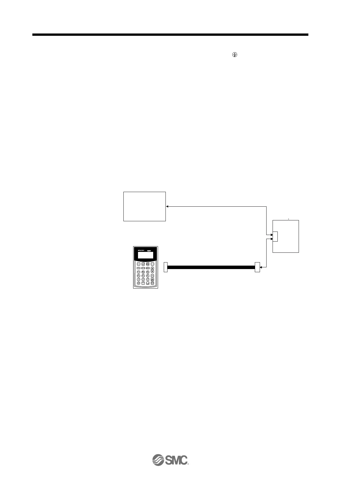
Controller or parameter units can also be connected via the CN3 connector, enabling RS-422/RS-485 communication. Note
that using the USB communication function (CN5 connector) prevents the RS-422/RS-485 communication function (CN3
connector) from being used, and vice versa. They cannot be used together.
PRU03
MR-PRU03
parameter unit
CN3
Servo amplifier
or
10BASE-T cable, etc. (EIA568-compliant)
RS-422/RS-485
compatible
controller
This connection is not required for RD75D, LD75D and QD75D. However, to enhance noise tolerance, it is recommended to
connect LG of driver and control common depending on the positioning module.
When not using the STO function, attach the short-circuit connector came with a driver.
Configure a circuit to turn off EM2 when the main circuit power is turned off to prevent an unexpected restart of the driver.
Plus and minus of the power of source interface are the opposite of those of sink interface.
CLEAR and CLEARCOM of source interface are interchanged to sink interface.
When a command cable for connection with the controller side malfunctions due to disconnection or noise, a position
mismatch can occur. To avoid position mismatch, it is recommended that Encoder A-phase pulse and Encoder B-phase pulse
be checked.
MITSUBISHI
ELECTRIC SYSTEM &
SERVICE CO., LTD

 Loading...