(2) Point table
(a) Point table setting
1 to 255 point tables can be set. To use point table No. 16 to 255, enable DI4 (Point table No.
selection 5) to DI7 (Point table No. selection 8) with "Device Setting" on Setup software (MR
Configurator2
TM
).
Set point tables using Setup software (MR Configurator2
TM
) or the operation section of the driver.
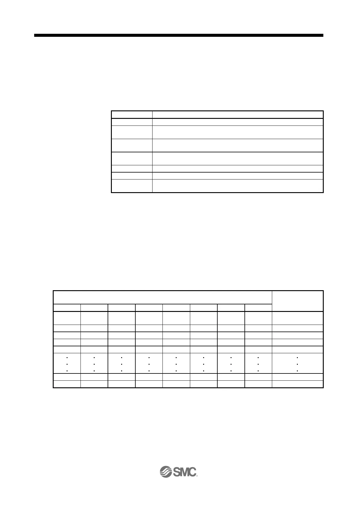
The following table lists what to set. Refer to section 4.2.2 for details of the settings.
Set the position data for movement.
Set the command speed of the servo motor for execution of positioning.
Acceleration
time constant
Set the acceleration time constant.
Deceleration
time constant
Set the deceleration time constant.
Set the waiting time when performing automatic continuous operation.
Set when performing automatic continuous operation.
Outputs the first digit and the second digit of the M code in 4-bit binary
respectively.
(b) Selection of point tables
Using the input signal or the communication function, select the point table No. with the
communication command from the PC or PLC...etc such as a personal computer.
The following table lists the point table No. selected in response to the input signal and the
communication command.
However, when using the input signal to select the point table No., you can only use point table No.
1 to 15 in the initial status.
To use point table No. 16 to 255, enable input signals DI4 (Point table No. selection 5) to DI7 (Point
table No. selection 8) with "Device Setting" on Setup software (MR Configurator2
TM
).
When using the communication function to select the point table No., refer to chapter 10.
0 (for home
position return)

 Loading...