17.Positioning mode (pushing operation)
To prevent electric shock, be sure to connect the protective earth (PE) terminal (marked terminal) of the driver to the
protective earth (PE) of the control panel.
Do not mistake the direction of the diode. If it is connected in reverse, the driver will break down and no signal will be
output, and the protection circuit such as EM2 (forced stop 2) may not operate.
Be sure to install a forced stop switch (B contact).
Supply 24 VDC ± 10% power from the outside for the interface. Set the current capacity of these power supplies to 500 mA
in total. 500 mA is the value when all input / output signals are used. The current capacity can be reduced by reducing the
number of input / output points. Refer to the current required for the interface described in Section 3.9.2 (1). The 24 V DC
power supply can be used for both input and output signals.
During operation, be sure to turn on EM2 (forced stop 2), LSP (forward stroke end) and LSN (reverse stroke end). (B
contact)
ALM (failure) is turned on when no alarm is generated. (B contact)
Signals with the same name are connected inside the driver.
[Pr. PD04], [Pr. PD06], [Pr. PD08], [Pr. PD10], [Pr. PD12], [Pr. PD14], [Pr. PD18], [Pr. PD20], [Pr. PD22], [Pr. PD44], and
[Pr. PD46] enable TL (external torque limit selection) to be used. (Refer to Section 3.6.1 (5))
Use the setup software (MR Configurator2
TM
). (See section 11.7)
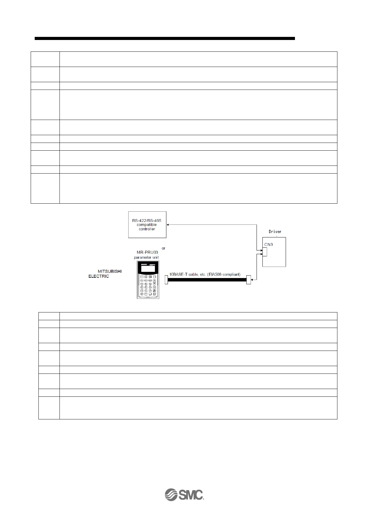
The upper side or parameter unit can be connected using RS-422 / RS-485 communication of CN3 connector. However,
the USB communication function (CN5 connector) and the RS-422 / RS-485 communication function (CN3 connector) are
exclusive functions. They cannot be used at the same time. The parameter unit MR-PRU03 cannot read or write the
pushing torque of the point table setting data in the point table pushing operation.
When inputting negative voltage, use an external power supply.
When not using the STO function, attach the short-circuit connector provided with the driver.
To prevent an unexpected restart of the driver, configure a circuit that turns off EM2 when the main circuit power is turned
off.
In case of sink I / O interface.
[Pr. PD04], [Pr. PD06], [Pr. PD08], [Pr. PD10], [Pr. PD12], [Pr. PD14], [Pr. PD18], [Pr. PD20], [Pr. The device can be
changed using [PD22], [Pr. PD44] and [Pr. PD46].
No output device is assigned in the initial state. Assign output devices as required with [Pr. PD47].
The listed devices are the recommended assignments. The device can be changed using [Pr. PD23] to [Pr. PD26] and [Pr.
PD28].
DI2 and DI3 are assigned to the CN1-10 pin and CN1-35 pin in the initial state.
When input devices are assigned to the CN1-10 and CN1-35 pins, use the sink input interface and supply 24 V DC + to the
OPC (open collector sink interface power supply input). Not available for source input interface. In the positioning mode,
input devices (DI2 and DI3) are assigned in the initial state.

 Loading...