EasyManuals Logo
Home>SMC Networks>DC Drives>LECSB2-T Series

SMC Networks LECSB2-T Series User Manual

SMC Networks LECSB2-T Series
945 pages
To Next Page IconTo Next Page
To Previous Page IconTo Previous Page
Page #89 background imageLoading...
Page #89 background image
3. SIGNALS AND WIRING
3 - 45
Normally, connect as follows.
Japan resistor
RRS10 or equivalent
DICOM
P15R
VLA
LG
SD
Servo amplifier
SP1
(Note)
2 kΩ
2 kΩ
24 V DC
Note.
This diagram shows sink I/O interface. For source I/O interface, refer to section
3.9.3.
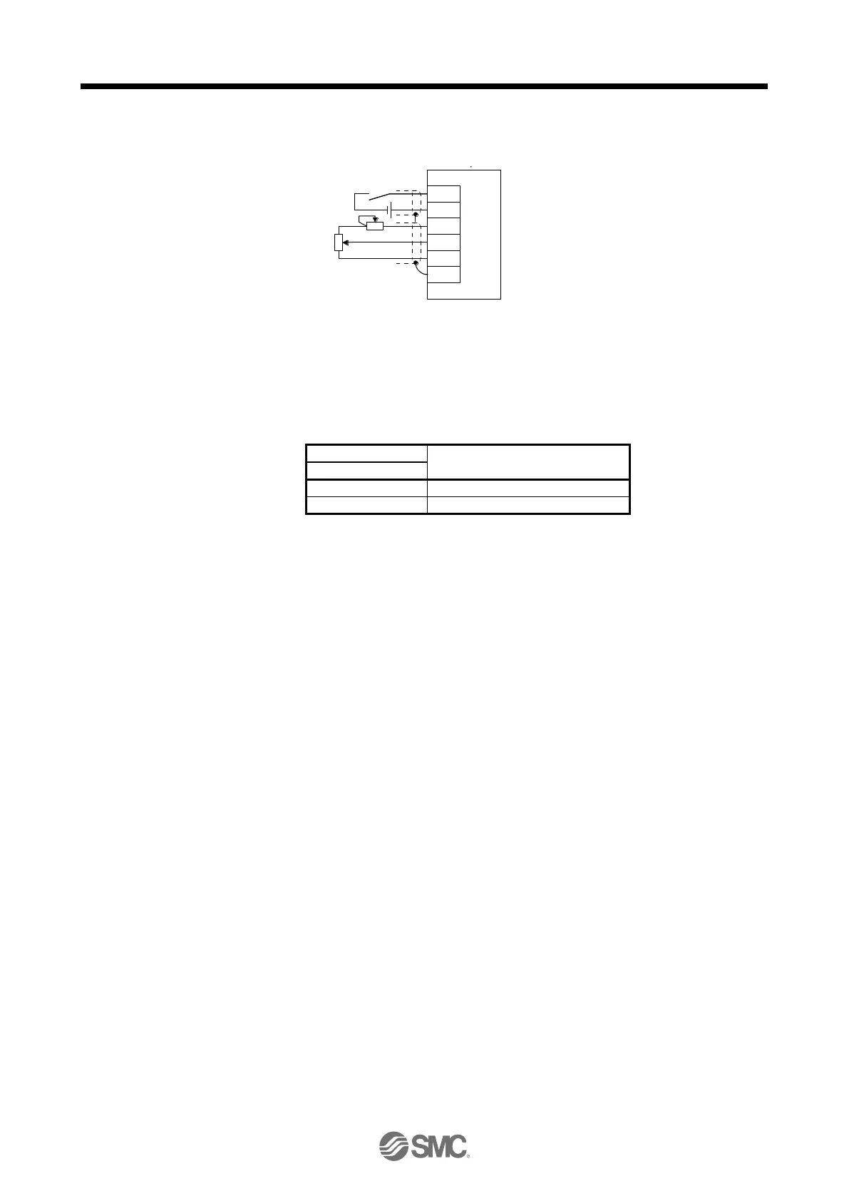
(b) Speed limit value selection
Select any of the speed settings by the internal speed limit 1 and by VLA (Analog speed limit) using
SP1 (Speed selection 1) as follows.
(Note) Input device
Speed command value
SP1
0
VLA (Analog speed limit)
1
Pr. PC05 Internal speed limit 1
Note.
0: Off
1: On
You can change the speed during rotation. To accelerate/decelerate, set acceleration/deceleration
time constant in [Pr. PC01] or [Pr. PC02].
When the internal speed limit 1 is used to command a speed, the speed does not vary with the
ambient temperature.
(c) VLC (Limiting speed)
As in section 3.6.3 (3) (c)
(5) Torque control in torque control mode
As in section 3.6.3 (1)
(6) Torque limit in torque control mode
As in section 3.6.3 (2)
Driver

Table of Contents

Questions and Answers:

Question and Answer IconNeed help?

Do you have a question about the SMC Networks LECSB2-T Series and is the answer not in the manual?

SMC Networks LECSB2-T Series Specifications

General IconGeneral
BrandSMC Networks
ModelLECSB2-T Series
CategoryDC Drives
LanguageEnglish