5 OPERATION
5.72 MHL360 E
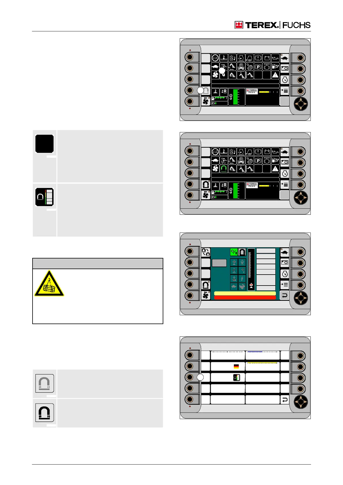
5.20.1.2 Selecting the display mode of the
main control display
You can select two display modes for working
with the magnetic plate: normal magnet sys-
tem display or comfort magnet system dis-
play. You make this selection in the display
settings menu (202/7).
h Chapter 4.5.11 Display settings
When the ignition is switched on, the indicator
(199/27) shows which display mode is active.
No symbol: Normal magnet system dis-
play
• Display for operating state of magnet
system and loading machine.
• Switch the magnet system operating
mode in the operating mode selection
menu.
Symbol: The comfort magnet system
display appears during magnet system
operation.
• Detailed display for operating state of
magnet system.
• Operating mode can be changed direct-
ly without the need to switch menus.
5.20.1.3 Magnet system and diesel engine
Danger of injury due to falling
material
• Set down the material to be load-
ed before turning off the diesel
engine!
In an emergency: Administer first
aid, seek treatment from a doctor
The diesel engine continually drives the gen-
erator in order to produce power. On the main
control display, the symbolized magnet on the
button (199/6) indicates the status of the
magnet system.
Gray symbol: Magnet system not ready
for switching on. Diesel engine not yet
started or communication fault.
Black symbol: Magnet system ready to
operate. Can be switched on.
►
If you have not already done so, start the
diesel engine.
09 :43 11 .03. 20 11
XXX / XXXX / LE XX X
18 00 U PM
0 5 1 0 15 20 2 5
95°C 7 5°C
0 ½ 1
9 %
120 0
24.X V
120 %
0 %
100 %
80 %
60 %
40 %
20 %
F
BSB51131
6
27
Fig. 199 Ignition switched on
09 :43 11 .03. 20 11
XXX / XXXX / LE XX X
18 00 U PM
0 5 1 0 15 20 2 5
95°C 7 5°C
0 ½ 1
9 %
120 0
24.X V
120 %
0 %
100 %
80 %
60 %
40 %
20 %
F
BSB51141
Fig. 200 Working with the normal magnet system
display
09 :43 11 .03. 2 011
XX X / XXXX / LE X X X
18 00 U PM
0 5 1 0 15 20 2 5
95°C 7 5°C
0 ½ 1
9 %
120 0
24.X V
120 %
0 %
100 %
80 %
60 %
40 %
20 %
F
100
90
80
70
60
50
40
30
20
10
0 %
CAN
M AG NE T V OL TA GE
M AG NE T C UR R E NT
M AG NE T P OW ER
E L EC T R. T EM P.
TO RQU E
S PE ED
M C U -P LC ST AT US
0
0 [1/min]
0 [N m]
0 [° C]
0 [W ]
0 [A]
0 [V]
ISO
Se lftest
BSB51142
0 kOhm
Fig. 201 Working with the comfort magnet system
display
09 :43 11 .03. 20 11
XXX / XXXX / LE XX X
18 00 U PM
0 5 1 0 15 20 2 5
95°C 7 5°C
0 ½ 1
9 %
120 0
24.X V
120 %
0 %
100 %
80 %
60 %
40 %
20 %
F
F1
F2
F3
F4
F6
F7
F8
F9
F5
Brig htne ss D ay
10 : 43 : 55
06 . 08 . 2011
ESC
Language 0
10 0
0 50 100
Brig htne ss N ight
50
0 50 100
Brig htne ss S t a ndby
1
0 50 100
Design Colour 1
BSB51163
7
Fig. 202 Display settings
7 Design/Color: Activates or deactivates the comfort
magnet system display or changes its color