5 OPERATION
5.76 MHL360 E
5.20.1.5 Operating the magnet system with
the comfort magnet system dis-
play
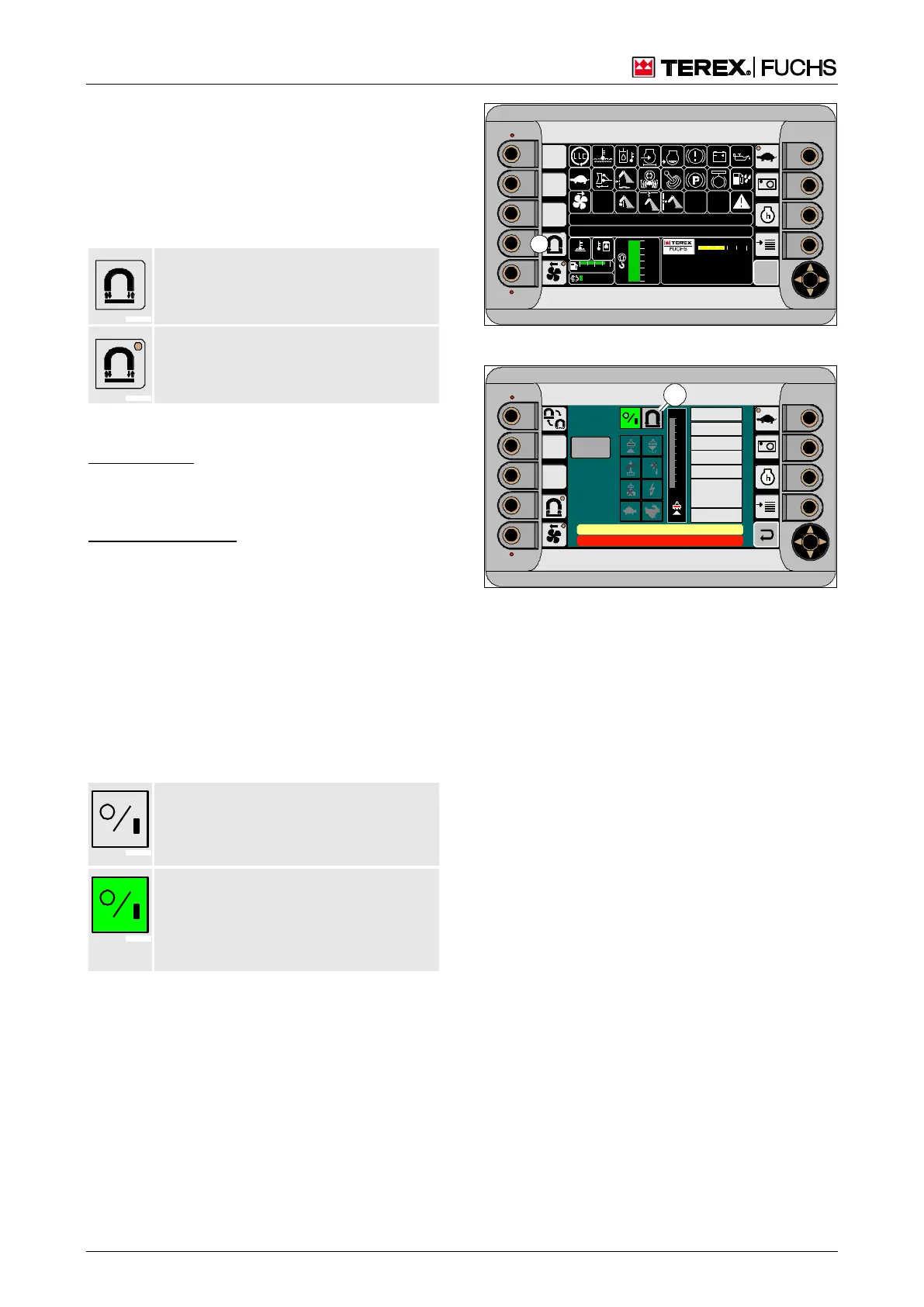
Button (208/6) is used for switching on or
switching off the magnet system. The symbol-
ized LED indicates the status of the button.
LED off: Button deactivated, allowing
the magnet system to be switched off.
LED on: Button activated, allowing the
magnet system to be switched on.
Switching on the magnet system
Function keys
►
Briefly press function key (208/6) in order
to activate the button.
Multifunction button
►
With the mini-joystick, navigate the focus to
button (208/6).
►
Briefly press the multifunction button in
order to activate the other button.
The comfort magnet system display shows
current operating data and operating states in
detail, and allows you to change the operating
mode and carry out a manual ISO guard func-
tion test. Indicator (209/1) indicates the status
of the magnet system.
Black background color: Magnet system
not ready for magnetization (generator
speed too low or ISO guard function test
running).
Green background: Magnet system
switched on and ready to operate. Mag-
netic plate magnetization and demag-
netization possible depending on the
selected operating mode.
h Chapter 4.5.7 Magnet system (optional)
Switching off the magnet system
Prerequisite: Magnetic plate demagnetized.
►
Deactivate button (208/6) using function
key or multifunction button.
If the LED goes out and the normal magnet
system display appears, this means the mag-
net system is switched off.
09 :43 11 .03. 20 11
XXX / XXXX / LE XX X
18 00 U PM
0 5 1 0 15 20 2 5
95°C 7 5°C
0 ½ 1
9 %
120 0
24.X V
120 %
0 %
100 %
80 %
60 %
40 %
20 %
F
6
BSB51149
Fig. 208 Magnet system still switched off
09 :43 11 .03. 2 011
XX X / XXXX / LE X X X
18 00 U PM
0 5 1 0 15 20 2 5
95°C 7 5°C
0 ½ 1
9 %
120 0
24.X V
120 %
0 %
100 %
80 %
60 %
40 %
20 %
F
100
90
80
70
60
50
40
30
20
10
0 %
CAN
M AG NE T V OL TA GE
M AG NE T C UR R E NT
M AG NE T P OW ER
E L EC T R. T EM P.
TO RQU E
S PE ED
M C U -P LC ST AT US
0
0 [1/min]
0 [N m]
0 [° C]
0 [W ]
0 [A]
0 [V]
ARB EITSHYDRAULIK IST GE SPE RRT
FEHLE RMELDUNG
ISO
0 kOhm
Se lftest
BSB51132
1
Fig. 209 Magnet system switched on (with comfort
magnet system display)