Arm
®
CoreLink™ GIC-600AE Generic Interrupt Controller
Technical Reference Manual
Document ID: 101206_0003_04_en
Issue: 04
Functional Safety
The clocks that are used for stitched domain modules, and the top level, are:
<domain>clk This signal clocks the primary mission-critical logic
<domain>clk_fdc This signal clocks the redundant logic
The functional requirements for the clk and clk_fdc signals are:
•
clk and clk_fdc must be edge-synchronous and run at the same frequency
•
clk and clk_fdc must start and stop at the same time
Asynchronous inputs to clk and clk_fdc
Some signals such as qreqn[_*] and interrupt wires have built-in or optional inverters and
synchronizers. These inverters and synchronizers are set by the *_INV and *_SYNC parameters,
respectively. All other signals belonging to the same module must be synchronous to the clock.
For more information, see 3.2.4 Redistributor PPI signals on page 33 and 3.5.2 SPI Collator wires
on page 42.
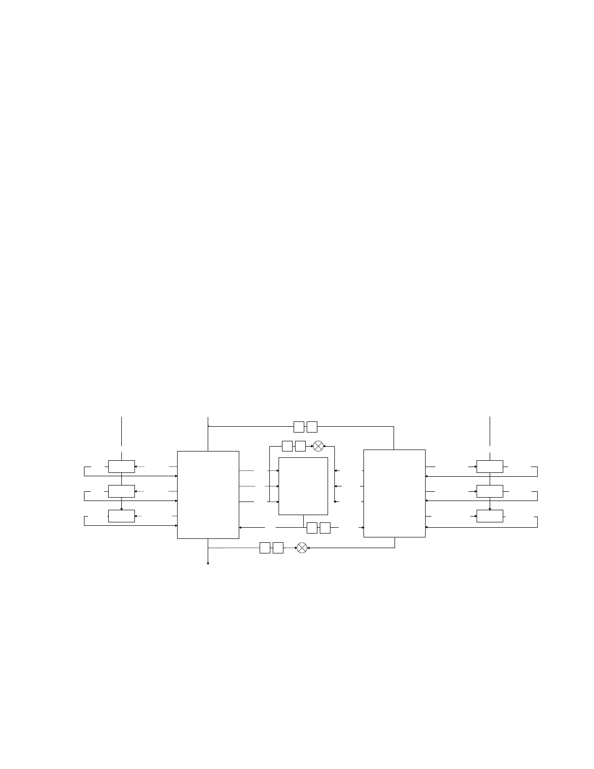
6.5.1.1 Block-level clocking
The GICD, GICR, and ITS blocks all have a similar clocking structure.
The following figure shows an example clocking structure for the GICR.
Figure 6-5: GICR block-level clocking example
F
F
wdata
RAM
rdata
rdata_fdc
F
F
wakeup_ppsgi
wakeup_up
wakeup_dn
we/ce
addr
PPI_noram
checker
F
wdata_fdc
addr_fdc
we/ce_fdc
ClkGate
wakeup_ppsgi_fdc
wakeup_up_fdc
wakeup_dn_fdc
clk_dn_fdc
clk_up_fdc
clk_ppsgi_fdc
clk_fdc
ClkGate
ClkGate
On the primary side, the clk signal is the always-on clock. It generates architecturally clock gated
versions of the clocks through the ClkGate cells. In Figure 6-5: GICR block-level clocking example
on page 213, the architecturally gated clocks are the clk_dn and clk_ppsgi signals.
On the redundant side, the clk_fdc signal works similarly but uses its own redundant ClkGate cells.
Copyright © 2018–2020, 2022 Arm Limited (or its affiliates). All rights reserved.
Non-Confidential
Page 213 of 268