The Electronics Pod Assembly (EPOD)
DSX™ System Service Manual 17-9
7 The free end of the twisted blue wire from the PSU/Filter Harness is connected to
the N (Load Side) terminal on the Filter.
8 When reinstalling the filter, orient it so that the two-terminal side faces the
capacitor in the EPOD enclosure.
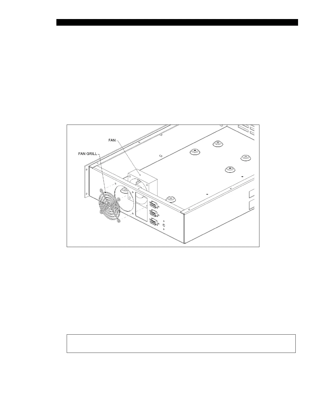
17.3.3.3. Removing and Replacing the EPOD Fan
The fan (Part No. 42200300) and fan grill (Part No. 6540154003) are fitted on the
enclosure as shown on Figure 17-7.
Figure 17-7 Fan Installation
The fan is secured using four M3 X 35mm Pan Head screws with four M3 Flat washers
and four M3 Nyloc Nuts. The red wire from the fan is attached to V3 positive (+) and the
black wire from the fan is attached to V3 negative (-) on the power supply.
When reinstalling the fan, feed wires of Fan through 175mm of Shrink Wrap Jacket (Part
No. 6540060001). The fan and fan grill (Part No. 6540150003) onto the enclosure as
shown, and secure using four M3X35 Pan Head Screws with four M3 Flat Washers on the
outside of the enclosure and four M3 Nyloc Nuts with four M3 Flat Washers on inside of
the enclosure.
Note: Ensure that the fan is properly installed so that fan wires are positioned
on the bottom of enclosure and towards the facia plate of enclosure.