3 - 44
Chapter 3 Removal and Replacement Procedures (RRPs)
Replacement
1) Insert the SHAFT PB (PL 3.1) into the PLATE ASSEMBLY BTM, and insert the GEAR BTM DMP
ONEWAY, GEAR PB L and GEAR BTM LOCK ONEWAY to the SHAFT PB.
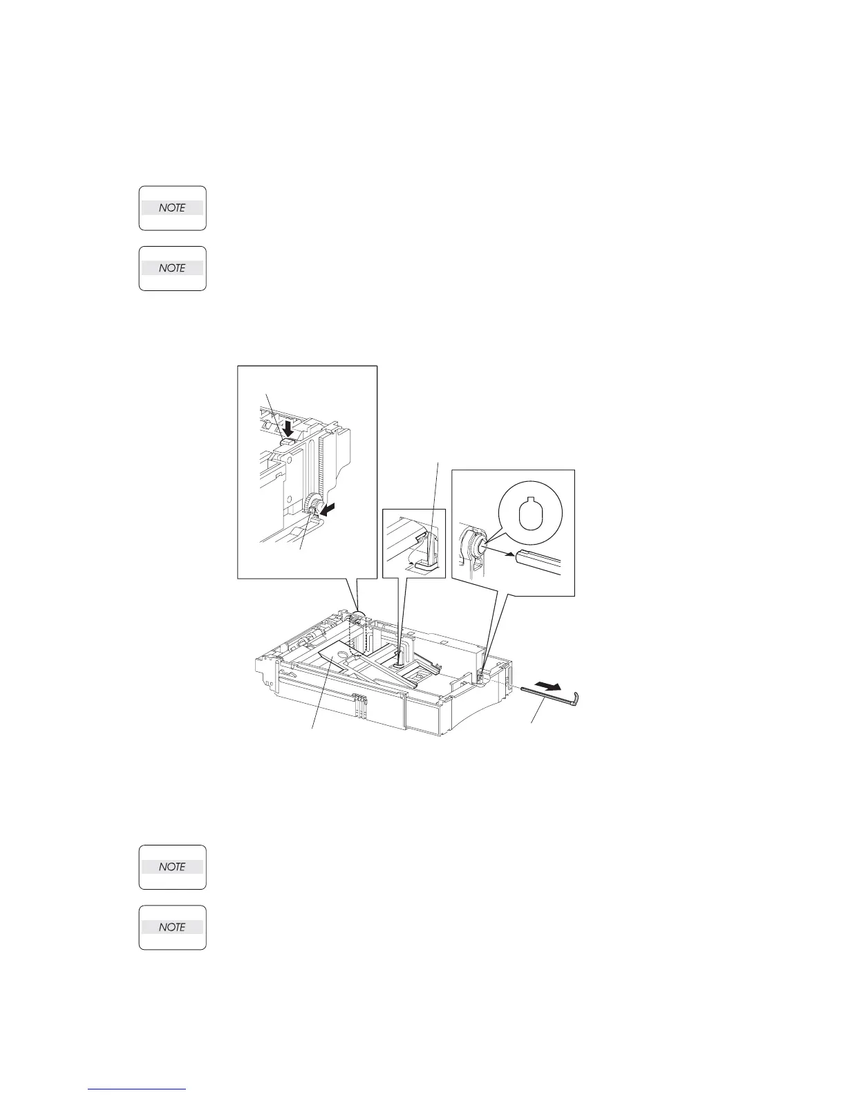
2) While disengaging the GEAR PB L, install the assembled PLATE ASSEMBLY BTM to the HOUS-
ING TOP 550 (PL 12.3).
When installing the PLATE ASSEMBLY BTM, be sure to put 2 SPRING BTM UP 550s
(PL 3.1.18) into the bosses on the back of the PLATE ASSEMBLY BTM (NOTE 1) (Figure
2).
Be sure to put 2 claws on the top of the PLATE ASSEMBLY BTM under the hooks on the
HOUSING TOP 550.(NOTE 2) (Figure 2).
3) Insert the link lever of the GUIDE INDICATOR 1 (PL 3.1) (Figure 2) into the hole of the PLATE
ASSEMBLY BTM (Figure 3).
Figure 3. Guide Indicator 3
4) Install the GEAR PB R (PL4.1.20) to the SHAFT PB (PL4.1.9), and secure it with the hook.
Be sure to install the hook of the GEAR PB R into the groove of the SHAFT PB.
When installing the PLATE GEAR LOCK 550, be sure to lift up the PLATE ASSEMBLY
BTM. If the PLATE ASSEMBLY BTM is inclined, a paper skew or jam may occur. Check
after the installation is completed.
5) While pressing down the hook of the HOUSING TOP 550, install the GUIDE ASSEMBLY SD R550
(PL 12.3) to the HOUSING TOP 550.
JG3027AA
GUIDE INDICATOR 3
(PL4.1.36)
GUIDE INDICATOR 1
LEVER BTM LOCK
(PL4.1.27)
STOPPER GEAR
(PL4.1.29)
PLATE ASSY BTM
(PL4.1.10)
(PL 3.1.27)
(PL 3.1.29)
(PL 3.1.10)
(PL 3.1.36)

 Loading...


