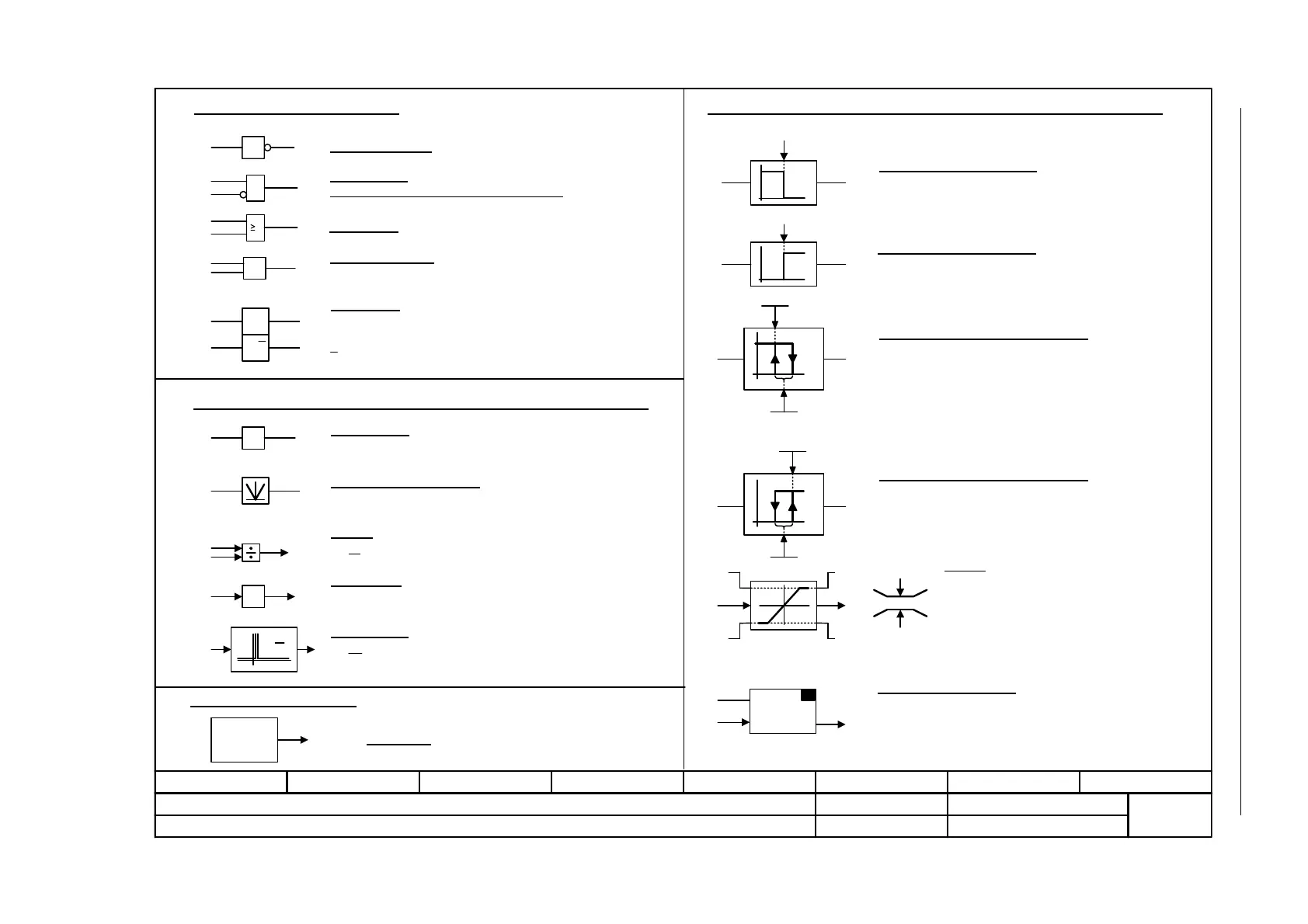
Fig. 2-2 1021 – Explanation of the symbols (Part 2)
- 1021 -
Function diagram
87654321
FP_1021_97_51.vsd
Explanations for the function diagrams
G120 CU230P-2
29.10.2009 V4.3
Explanation of the symbols (Part 2)
y = -x
y = |x|
y =
1
&
xy
xy
>0
-1
xy
x
2
x
1
y
S Q
R Q
S
y
x
1
0
0
1
y
x
S
y =
dt
dx
LU
LL MLL
MLU
xy
SET
S & H
xy
dx
dt
x
y
0
1
S
H
y
x
0
1
H
S
y
x
Symbols for logic functions
Logical inversion
AND element
with logical inversion of an input signal
R/S flip-flop
S = setting input
R = reset input
Q = non-inverted output
Q = inverted output
Symbols for computational and closed-loop control functions
Threshold value switch 1/0
Outputs at y a logical "1" if x < S.
Threshold value switch 0/1
Outputs at y a logical "1" if x > S.
Threshold value 1/0 with hysteresis
Outputs a logical "1" at y if x < S.
If x >= S + H then y returns to 0.
Threshold value 0/1 with hysteresis
Outputs a logical "1" at y if x > S.
If x <= S - H then y returns to 0.
Limiter
x is limited to the upper limit LU and the lower limit LL
and output at y.
The digital signals MLU and MLL have the value "1", if
the upper or lower limit is active.
Sample & Hold element
Sample and hold element.
y = x if SET = 1
(not retentively saved at POWER OFF)
Symbols for computational and closed-loop control functions
Sign reversal
Absolute value generator
Divider
Comparator
Output y = a logical "1", if the analog signal
x > 0, i.e. is positive.
Differentiator
Symbol for monitoring
Monitoring
Monitoring
Axxxxx
or
Fxxxxx
1
OR element
=1
x
1
y
x
2
Exclusiv-OR/XOR
y = 1 when x1 != x2 is.
or
x
1
x
2