To prevent an electric shock, always connect the protective earth (PE) terminal (marked ) of the driver to the protective
earth (PE) of the cabinet.
Connect the diode in the correct direction. If it is connected reversely, the driver will malfunction and will not output signals,
disabling EM2 (Forced stop 2) and other protective circuits.
The forced stop switch (normally closed contact) must be installed.
Supply 24 V DC ± 10% to interfaces from outside. The total current capacity is up to 500 mA. 500 mA is the value applicable
when all I/O signals are used. The current capacity can be decreased by reducing the number of I/O points. Refer to section
3.9.2 (1) that gives the current value necessary for the interface. A 24 V DC power supply can be used for both input signal
and output signal.
When starting operation, always turn on EM2 (Forced stop 2), LSP (Forward rotation stroke end) and LSN (Reverse rotation
stroke end) (normally closed contact).
ALM (Malfunction) turns on in normal alarm-free condition (normally closed contact).
The pins with the same signal name are connected in the driver.
TLA will be available when TL (External torque limit selection) is enabled with [Pr. PD04], [Pr. PD06], [Pr. PD08], [Pr. PD10],
[Pr. PD12], [Pr. PD14], [Pr. PD18], [Pr. PD20], [Pr. PD22], [Pr. PD44], and [Pr. PD46]. (Refer to section 3.6.1 (5))
Use Setup software (MR Configurator2
TM
) (Refer to section 11.7)
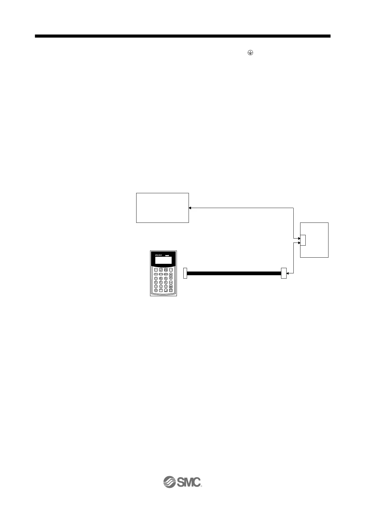
PC or PLC...etcs or parameter units can also be connected via the CN3 connector with the RS-422/RS-485 communication.
Note that using the USB communication function (CN5 connector) prevents the RS-422/RS-485 communication function (CN3
connector) from being used, and vice versa. They cannot be used together.
Use an external power supply when inputting a negative voltage.
When not using the STO function, attach the short-circuit connector came with a driver
Configure a circuit to turn off EM2 when the main circuit power is turned off to prevent an unexpected restart of the driver .
This diagram shows sink I/O interface.
The device can be changed with [Pr. PD04], [Pr. PD06], [Pr. PD08], [Pr. PD10], [Pr. PD12], [Pr. PD14], [Pr. PD18], [Pr. PD20],
[Pr. PD22], [Pr. PD44], and [Pr. PD46].
These output devices are not assigned by default. Assign the output device with [Pr. PD47] as necessary.
These devices are recommended assignments. The device can be changed by [Pr. PD23] to [Pr. PD26], and [Pr. PD28].
DI2 and DI3 are assigned to the CN1-10 and CN1-35 pins by default. When connecting a manual pulse generator, change
them with [Pr. PD44] and [Pr. PD46]. Refer to section 9.1 for details of the manual pulse generator.
Supply + of 24 V DC to OPC (Power input for open-collector sink interface) when input devices are assigned to the CN1-10 pin
and the CN1-35 pin. They are not used with source input interface. For the positioning mode, input devices (DI2 and DI3) are
assigned by default.
PRU03
MR-PRU03
parameter unit
CN3
Servo amplifier
or
10BASE-T cable, etc. (EIA568-compliant)
RS-422/RS-485
compatible controller

 Loading...