In the indexer method, assign the following input device to CN1-18 pin with [Pr.
PD10].
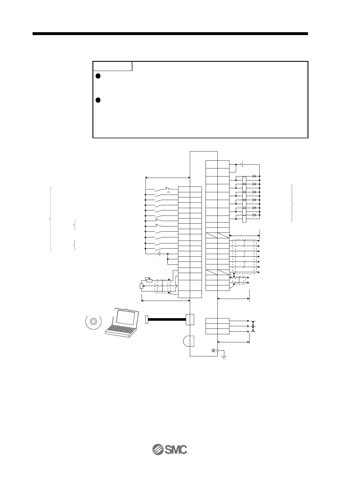
CN1-18: MD1 (Operation mode selection 2)
Assign the following output devices to CN1-22, CN1-23, and CN1-25 pins with
[Pr. PD23], [Pr. PD24], and [Pr. PD26].
CN1-22: CPO (Rough match)
CN1-23: ZP (Home position return completion)
CN1-25: MEND (Travel completion)
CN8
(Note 11)
Short-circuit connector
(Packed with the servo amplifier)
(Note 1)
(Note 2)
(Note 7)
CN1
(Note 7)
CN1
Plate
Servo amplifier
(Note 7)
CN6
2 m or shorter
3 MO1
1 LG
2 MO2
47 DOCOM
48
ALM
22 CPO
23 ZP
25 MEND
24 INP
(
4 LA
5 LAR
6 LB
7 LBR
34 LG
33 OP
SD
2 m or shorter
(
8 LZ
9 LZR
20
DICOM
21
DICOM
1
2 m or shorter
Upper limit
setting
28
27
Plate
SD
TLA
LG
P15R
+
(Note 10)
USB cable
(option)
CN5
(Note 9)
MR Configurator2
Personal
computer
24 V DC (Note 4, 13)
RA1
RA2
RA3
RA4
RA6
42
15
16
44
19
41
10
17
18
EM2
SON
MD0
LSN
DI0
DI1
DI2
ST1
MD1
Reverse rotation stroke end
Forced stop 2
Servo-on
Forward rotation stroke end
(Note 3, 5)
(Note 5)
± 10 V DC
± 10 V DC
Analog monitor 1
Analog monitor 2
Encoder A-phase pulse
(differential line driver)
Encoder B-phase pulse
(differential line driver)
Control common
Encoder Z-phase pulse
(open-collector)
Encoder Z-phase pulse
(differential line driver)
Malfunction ( Note 6)
10 m or shorter
(Note 12)
Main circuit
power supply
46
DOCOM
10 m or shorter
24 V DC (Note 4, 13)
49
13
14
RD
(Note 15)
(Note 15)
Rough match
Home position
return completion
Travel completion
In-position
Ready
(Note 16)
RA5
SIG
LSP
DI3
45
43
35
Operation mode selection 1
Forward rotation start
Operation mode selection 2
External limit/Rotation direction decision/
Automatic speed selection
Next station No. selection 1
Next station No. selection 2
Next station No. selection 3
Next station No. selection 4
(Note 17, 18)
(Note 14)
(Note 8) Analog torque limit
+10 V/maximum torque
Control common
12
OPC

 Loading...