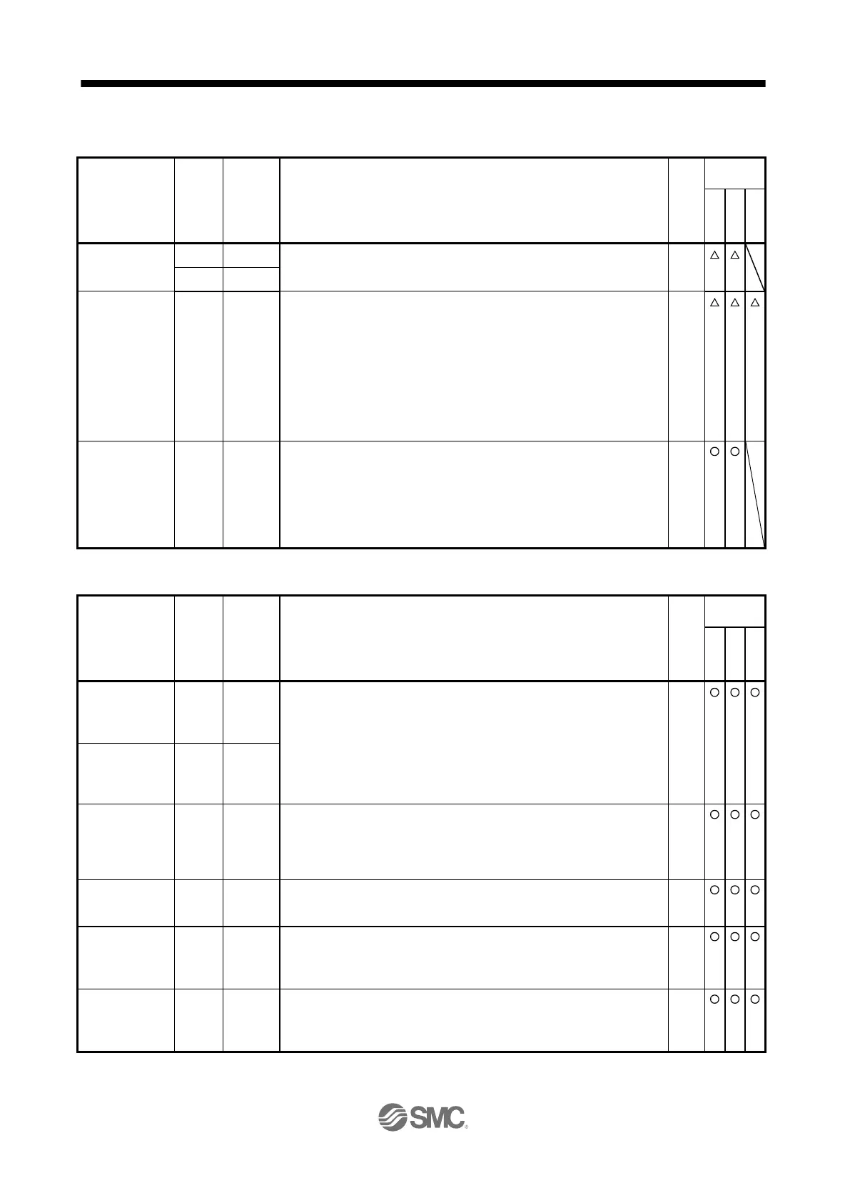
Connect the manual pulse generator (MR-HDP01).
When using the signal, enable PP and NP with [Pr. PD44] and [Pr. PD46].
When using the signal, enable TL (External torque limit selection) with [Pr.
PD04], [Pr. PD06], [Pr. PD08], [Pr. PD10], [Pr. PD12], [Pr. PD14], [Pr.
PD18], [Pr. PD20], [Pr. PD22], [Pr. PD44], and [Pr. PD46].
When TLA is enabled, torque is limited in the full servo motor output torque
range. Apply 0 V to +10 V DC between TLA and LG. Connect the positive
terminal of the power supply to TLA. The maximum torque is generated at
+10 V. (Refer to section 3.6.1 (5))
If a value equal to or larger than the maximum torque is inputted to TLA,
the value is clamped at the maximum torque.
Resolution: 10 bits
The signal controls the servo motor setting speed by applying -10 V to +10
V to between VC and LG. The percentage will be 0% with -10 V, 100%
with 0 V, and 200% with +10 V to the setting speed of the servo motor.
Resolution: 14 bits or equivalent
Setting [Pr. PC60] to "_ _ 1 _" increases the analog input resolution to 16
bits.
Encoder A-
phase pulse
(differential line
driver)
These devices output pulses of encoder output pulse set in [Pr. PA15] in
the differential line driver type.
In CCW rotation of the servo motor, the encoder B-phase pulse lags the
encoder A-phase pulse by a phase angle of π/2.
The relation between rotation direction and phase difference of the A-
phase and B-phase pulses can be changed with [Pr. PC19].
Encoder B-
phase pulse
(differential line
driver)
Encoder Z-
phase pulse
(differential line
driver)
The encoder zero-point signal is outputted in the differential line driver
type. One pulse is outputted per servo motor revolution. This turns on
when the zero-point position is reached. (negative logic)
The minimum pulse width is about 400 μs. For home position return using
this pulse, set the creep speed to 100 r/min or less.
Encoder Z-
phase pulse
(open-collector)
The encoder zero-point signal is outputted in the open-collector type.
This is used to output the data set in [Pr. PC14] to between MO1 and LG in
terms of voltage.
Output voltage: ±10 V
Resolution: 10 bits or equivalent
This signal outputs the data set in [Pr. PC15] to between MO2 and LG in
terms of voltage.
Output voltage: ±10 V
Resolution: 10 bits or equivalent

 Loading...