EasyManuals Logo
Home>SMC Networks>DC Drives>LECSB2-T Series

SMC Networks LECSB2-T Series User Manual

SMC Networks LECSB2-T Series
945 pages
To Next Page IconTo Next Page
To Previous Page IconTo Previous Page
Page #65 background imageLoading...
Page #65 background image
3. SIGNALS AND WIRING
3 - 21
Pin No.
(Note 1)
I/O
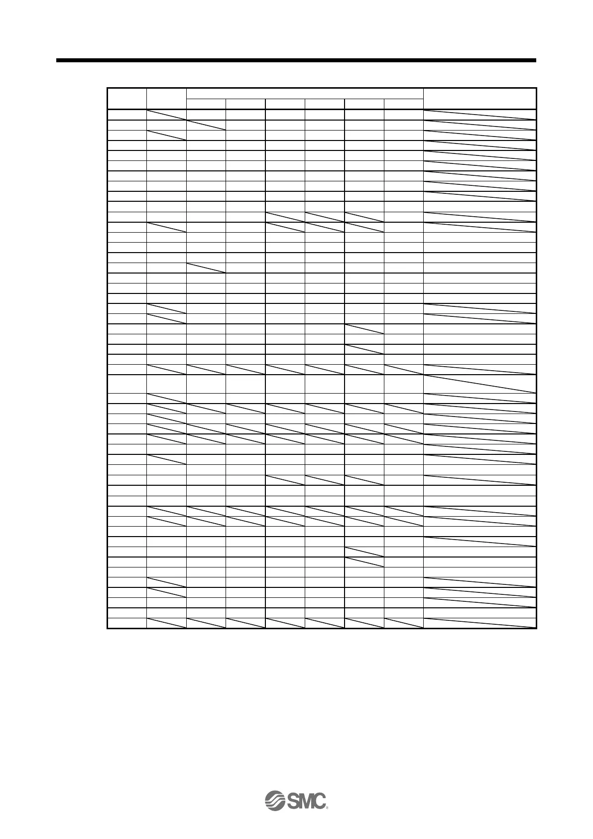
(Note 2) I/O signals in control modes
Related parameter
P
P/S
S
S/T
T
T/P
1
P15R
P15R
P15R
P15R
P15R
P15R
2
I
-/VC
VC
VC/VLA
VLA
VLA/-
3
LG
LG
LG
LG
LG
LG
4
O
LA
LA
LA
LA
LA
LA
5
O
LAR
LAR
LAR
LAR
LAR
LAR
6
O
LB
LB
LB
LB
LB
LB
7
O
LBR
LBR
LBR
LBR
LBR
LBR
8
O
LZ
LZ
LZ
LZ
LZ
LZ
9
O
LZR
LZR
LZR
LZR
LZR
LZR
10
I
PP
PP/-
(Note 6)
(Note 6)
(Note 6)
-/PP
PD43/PD44
11
I
PG
PG/-
-/PG
12
OPC
OPC/-
-/OPC
13
O
(Note 4)
(Note 4)
(Note 4)
(Note 4)
(Note 4)
(Note 4)
PD47
14
O
(Note 4)
(Note 4)
(Note 4)
(Note 4)
(Note 4)
(Note 4)
PD47
15
I
SON
SON
SON
SON
SON
SON
PD03/PD04
16
I
-/SP2
SP2
SP2/SP2
SP2
SP2/-
PD05/PD06
17
I
PC
PC/ST1
ST1
ST1/RS2
RS2
RS2/PC
PD07/PD08
18
I
TL
TL/ST2
ST2
ST2/RS1
RS1
RS1/TL
PD09/PD10
19
I
RES
RES
RES
RES
RES
RES
PD11/PD12
20
DICOM
DICOM
DICOM
DICOM
DICOM
DICOM
21
DICOM
DICOM
DICOM
DICOM
DICOM
DICOM
22
O
INP
INP/SA
SA
SA/-
-/INP
PD23
23
O
ZSP
ZSP
ZSP
ZSP
ZSP
ZSP
PD24
24
O
INP
INP/SA
SA
SA/-
-/INP
PD25
25
O
TLC
TLC
TLC
TLC/VLC
VLC
VLC/TLC
PD26
26
27
I
TLA
(Note 3)
TLA
(Note 3)
TLA
(Note 3)
TLA/TC
TC
TC/TLA
28
LG
LG
LG
LG
LG
LG
29
30
LG
LG
LG
LG
LG
LG
31
32
33
O
OP
OP
OP
OP
OP
OP
34
LG
LG
LG
LG
LG
LG
35
I
NP
NP/-
(Note 6)
(Note 6)
(Note 6)
-/NP
PD45/PD46
36
I
NG
NG/-
-/NG
37
I
PP2
PP2/-
(Note 7)
(Note 7)
(Note 7)
-/PP2
PD43/PD44
38
I
NP2
NP2/-
(Note 7)
(Note 7)
(Note 7)
-/NP2
PD45/PD46
39
40
41
I
CR
CR/SP1
SP1
SP1/SP1
SP1
SP1/CR
PD13/PD14
42
I
EM2
EM2
EM2
EM2
EM2
EM2
43
I
LSP
LSP
LSP
LSP/-
-/LSP
PD17/PD18
44
I
LSN
LSN
LSN
LSN/-
-/LSN
PD19/PD20
45
I
LOP
LOP
LOP
LOP
LOP
LOP
PD21/PD22
46
DOCOM
DOCOM
DOCOM
DOCOM
DOCOM
DOCOM
47
DOCOM
DOCOM
DOCOM
DOCOM
DOCOM
DOCOM
48
O
ALM
ALM
ALM
ALM
ALM
ALM
49
O
RD
RD
RD
RD
RD
RD
PD28
50
Note 1.
I: Input signal, O: Output signal
2.
P: Position control mode, S: Speed control mode, T: Torque control mode, P/S: Position/speed control change
mode, S/T: Speed/torque control change mode, T/P: Torque/position control change mode
3.
TLA will be available when TL (External torque limit selection) is enabled with [Pr. PD03] to [Pr. PD22].
4.
Output devices are not assigned by default. Assign the output devices with [Pr. PD47] as necessary.
6.
This is available as an input device of sink interface. Input devices are not assigned by default. Assign the input
devices with [Pr. PD43] to [Pr. PD46] as necessary. Supply + of 24 V DC to CN1-12 pin.
7.
This is available as an input device of source interface. Input devices are not assigned by default. Assign the
input devices with [Pr. PD43] to [Pr. PD46] as necessary.

Table of Contents

Questions and Answers:

Question and Answer IconNeed help?

Do you have a question about the SMC Networks LECSB2-T Series and is the answer not in the manual?

SMC Networks LECSB2-T Series Specifications

General IconGeneral
BrandSMC Networks
ModelLECSB2-T Series
CategoryDC Drives
LanguageEnglish