3. SIGNALS AND WIRING
3 - 26
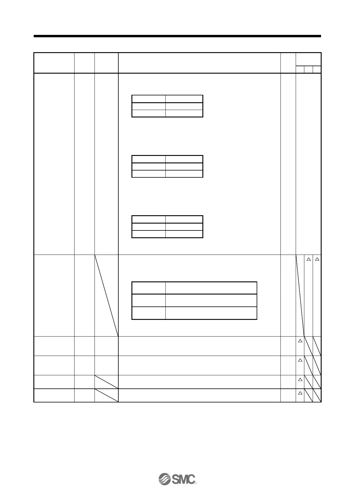
«Position/speed control change mode»
This is used to select the control mode in the position/speed control
switching mode.
Refer to
Function
and
application.
«Speed/torque control change mode»
This is used to select the control mode in the speed/torque control
switching mode.
«Torque/position control change mode»
This is used to select the control mode in the torque/position control
switching mode.
Second
acceleration/dece
leration selection
The device allows selection of the acceleration/deceleration time constant
at servo motor rotation in the speed control mode or torque control mode.
The s-pattern acceleration time constant and deceleration time constant is
always uniform.
Acceleration/deceleration time constant
Pr. PC01 Acceleration time constant
Pr. PC02 Deceleration time constant
Pr. PC30 Acceleration time constant 2
Pr. PC31 Deceleration time constant 2
This is an ABS transfer mode request device.
When "_ _ _ 1" is set in [Pr. PA03] and absolute position detection system
by DIO is selected, CN1-17 pin will become ABSM. (Refer to chapter 12.)
This is an ABS request device.
When "_ _ _ 1" is set in [Pr. PA03] and absolute position detection system
by DIO is selected, CN1-18 pin will become ABSR. (Refer to chapter 12.)
 Loading...