3. SIGNALS AND WIRING
3 - 28
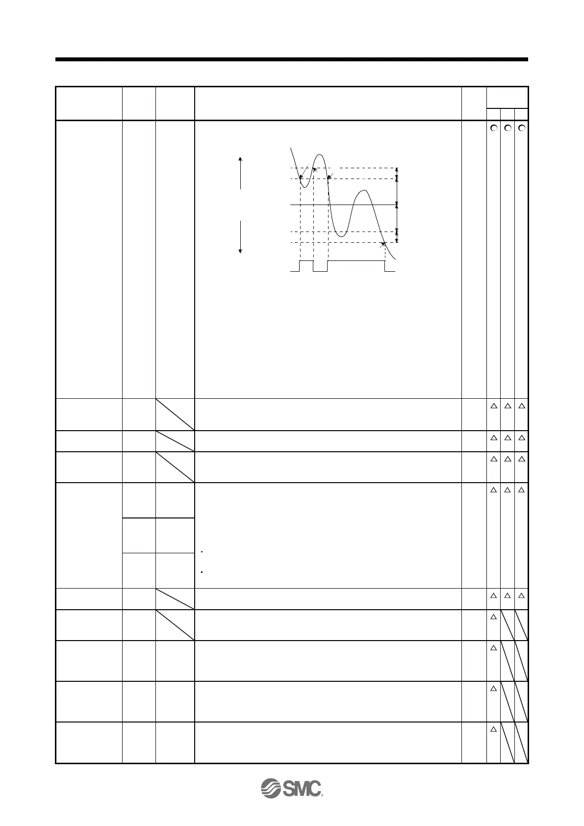
ZSP turns on when the servo motor speed is zero speed (50 r/min) or less.
Zero speed can be changed with [Pr. PC17].
OFF
ON
Servo motor
speed
20 r/min
(Hysteresis width)
[Pr. PC17]
20 r/min
(Hysteresis width)
OFF level
-70 r/min
ON level
-50 r/min
ON level
50 r/min
OFF level
70 r/min
0 r/min
[Pr. PC17]
ZSP
(Zero speed
detection)
1)
3)
2)
4)
Forward
rotation
direction
Reverse
rotation
direction
ZSP will turn on when the servo motor is decelerated to 50 r/min (at 1)),
and will turn off when the servo motor is accelerated to 70 r/min again (at
2)).
ZSP will turn on when the servo motor is decelerated again to 50 r/min (at
3)), and will turn off when the servo motor speed has reached -70 r/min (at
4)).
The range from the point when the servo motor speed has reached on
level, and ZSP turns on, to the point when it is accelerated again and has
reached off level is called hysteresis width.
Hysteresis width is 20 r/min for this driver.
Electromagnetic
brake interlock
When using the device, set operation delay time of the electromagnetic
brake in [Pr. PC16].
When a servo-off status or alarm occurs, MBR will turn off.
When warning has occurred, WNG turns on. When a warning is not
occurring, WNG will turn off in 2.5 s to 3.5 s after power-on.
BWNG turns on when [AL. 92 Battery cable disconnection warning] or [AL.
9F Battery warning] has occurred. When the battery warning is not
occurring, BWNG will turn off in 2.5 s to 3.5 s after power-on.
To use these signals, set " _ _ _ 1" in [Pr. PD34].
This signal is outputted when an alarm occurs.
When an alarm is not occurring, respective ordinary signals are outputted.
For details of the alarm codes, refer to chapter 8.
When [Pr. PD34] is set to "_ _ _ 1", setting the following will trigger [AL. 37
Parameter error].
"_ _ _ 1" is set in [Pr. PA03] and the absolute position detection system
by DIO is selected.
MBR, DB, or ALM is assigned to the CN1-22 pin, CN1-23 pin, or CN1-
24 pin.
CDPS turns on during gain switching.
Absolute
position
undetermined
ABSV turns on when the absolute position is undetermined.
ABS
transmission
data bit 0
This is used to output ABS transmission data bit 0. When "Enabled
(absolute position detection system by DIO) (_ _ _ 1)" is selected in [Pr.
PA03], the CN1-22 pin will become ABSB0 only during ABS transfer
mode. (Refer to chapter 12.)
ABS
transmission
data bit 1
This is used to output ABS transmission data bit 1. When "Enabled
(absolute position detection system by DIO) (_ _ _ 1)" is selected in [Pr.
PA03], the CN1-23 pin will become ABSB1 only during ABS transfer
mode. (Refer to chapter 12.)
ABS
transmission
data ready
This is used to output ABS transmission data ready. When "Enabled
(absolute position detection system by DIO) (_ _ _ 1)" is selected in [Pr.
PA03], CN1-25 pin will become ABST only during ABS transfer mode.
(Refer to chapter 12.)
 Loading...