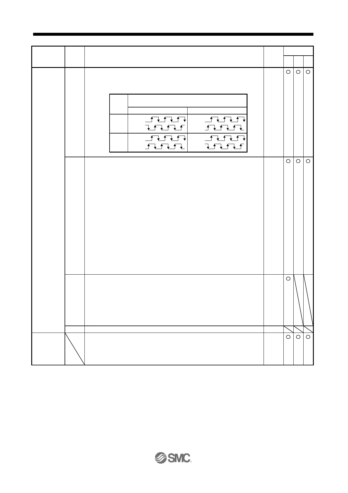
Encoder output pulse phase selection
Select an encoder pulse direction.
0: Increasing A-phase 90° in CCW or positive direction
1: Increasing A-phase 90° in CW or negative direction
Encoder output pulse setting selection
0: Output pulse setting
1: Division ratio setting
2: The same output pulse setting as command pulse
3: A-phase/B-phase pulse electronic gear setting
4: A/B-phase pulse through output setting
5: Command pulse input through output setting
When you select "1", the settings of [Pr. PA16 Encoder output pulses 2] will be
disabled.
When you select "2", the settings of [Pr. PA15 Encoder output pulses] and [Pr. PA16
Encoder output pulses 2] will be disabled. Additionally, it will be the servo motor side
pulse unit for the indexer method. When you select the setting, do not change the
settings in [Pr. PA06] and [Pr. PA07] after the power-on.
When "5" is set, the settings of [Pr. PA15 Encoder output pulses] and [Pr. PA16
Encoder output pulses 2] will be disabled. "Encoder output pulse phase selection (_ _
_ x)" and "Encoder selection for encoder output pulse (_ x _ _)" will be also disabled.
When [Pr. PA01] is set to other than "Point table method (_ _ _ 6)" and "Program
method (_ _ _ 7)", [AL. 37 Parameter error] occurs. When "5" is set, assign PP/PP2
with [Pr. PD44] and NP/NP2 with [Pr. PD46].
Selection of the encoders for encoder output pulse
Select an encoder used the encoder output pulses which the driver outputs.
0: Servo motor encoder
1: Load-side encoder
When "_ 1 0 _" is set to this parameter, [AL. 37 Parameter error] will occur.
This is only for the fully closed loop system.
If "1" is set other than in the fully closed loop system, [AL. 37 Parameter error] will
occur.
Specify a station No. of the driver for RS-422 and USB communication.
Always set one station to one axis of the driver Setting one station number to two or
more stations will disable a normal communication.
Setting range: 0 to 31
 Loading...